Hydraulics and Pneumatics: Unit II: Hydraulic Actuators and Control Components
directional control valves
Hydraulic Actuators and Control Components - Hydraulics and Pneumatics
Directional controls valves are used to determine the path of the fluid through which it should travel within a given circuit.
DIRECTIONAL CONTROL VALVES • Directional controls valves are used to determine the path of the fluid through which it should travel within a given circuit. • Directional control valves are shown by means of several connected squares. Number of squares - Indicates the number of switching positions possible. Arrow within square - Indicate the flow direction. Lines - Indicate how the ports are inter-connected in the various switching positions. • Naming convention for valve: Number of ports / Number of switching positions "-way valve". Example: 4/3 valve has 4 ports and 3 switching positions. • Table 7.3 presents the various standard symbols used for directional control valves. Table 7.3. Graphic symbols used for directional control valves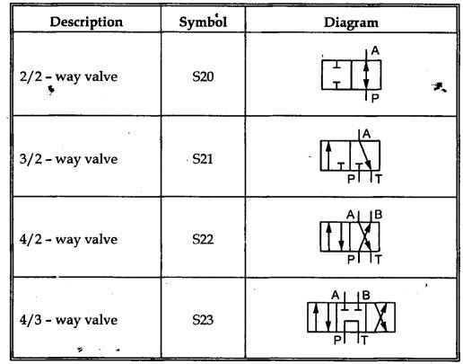
Hydraulics and Pneumatics: Unit II: Hydraulic Actuators and Control Components : Tag: : Hydraulic Actuators and Control Components - Hydraulics and Pneumatics - directional control valves
Related Topics
Related Subjects

Hydraulics and Pneumatics
ME3492 4th semester Mechanical Dept | 2021 Regulation | 4th Semester Mechanical Dept 2021 Regulation