Fluid Mechanics and Machinery: Unit 1: Fluid Properties and Flow Characteristics
Differential Manometer
Types, Construction Diagram, Working Principle
A differential manometer is used to measure the difference in pressure between two points in a pipe or in two different pipes.
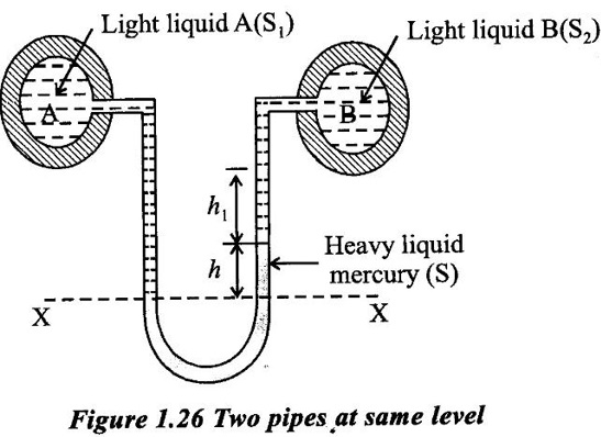
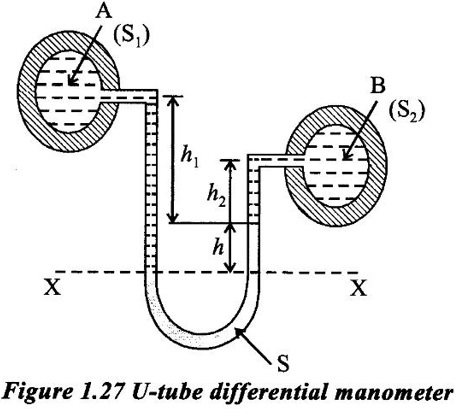
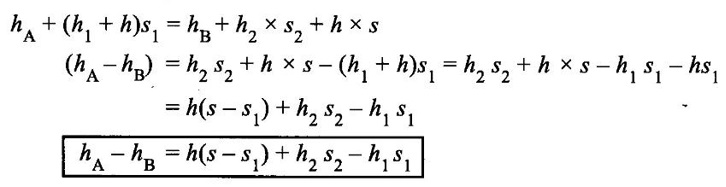
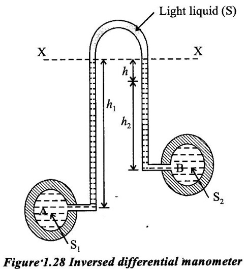
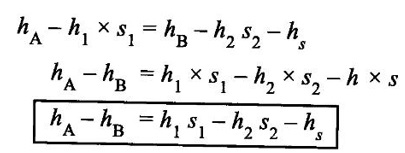
DIFFERENTIAL MANOMETER A differential manometer is used to measure the difference in pressure between two points in a pipe or in two different pipes. In simplest form a differential manometer consists of a U-tube containing a heavy liquid, whose two ends are connected to the points, whose difference of pressure is required to be found out following are the most community used types of differential manometers. (i) U-tube differential manometer (ii) Inverted U-tube differential manometer Case (i) Two pipes at same level The figure 1.28 shows a differential manometer whose two ends are connected with two different points A and B, at the same level and containing same liquid. Let, h = difference of mercury levels (heavy liquid) in the U-tube. h1 = distance of centre of A from the mercury level in the right limb. s1 = s2 = specific gravity of liquid at the two points A and B. s = specific gravity of heavy liquid or mercury in the U-tube hA = pressure head at A hB = pressure head at B W.K.T The pressure in left limb and right limb, above the datum line are equal. So, Pressure head in the left limb = hA + (h1 + h) s1 ... (1) Pressure head in the right limb = hB + h1 × s1 + h × s. ... (2) Equating the equations (1) and (2) hA + (h1 + h) s1 = hB + (h1 s1) + (h × s) hA - hB = h1 s1 + h × s − (h1 + h)s1 = h1 s1 + h × s − h1 s1 + h s1 hA - hB = h(s - s1). ... (3) Case (ii) Two pipes at different level The figure 1.27 shows a differential manometer whose two ends are connected to two different points A and B at different levels and containing different liquids. Let, h = difference of mercury levels in V-tube h1 = distance of the centre of A, from mercury level in the left limb h2 = distance of the centre of B, from mercury level in the right limb s1 = specific gravity of liquid in pipe A, s2 = specific gravity of liquid in pipe B s = specific gravity of heavy liquid or mercury hA = pressure head at A hB = pressure head at B Considering the pressure heads above the datum line X-X. Pressure head in the left limb = h′A + (h1 + h) s1 ... (1) Pressure head in the right limn = hB + (h2 × s2) + (h × s). ... (2) equating above two equations, The figure 1.28 shows an inversed U-tube differential manometer containing light liquid, whose two ends are connected to the points (A and B) whose difference of pressure is so be find out. Let the pressure at A is more than the pressure at B. Let; h1 = height of liquid in the left limb below the datum line X-X. h2 = height of liquid in she right limb below the datum line. h = difference of levels of the light liquid in the right and left limbs. s1 = specific gravity of the liquid in the left limb. s2 = specific gravity of the liquid in the right limb. s = specific gravity of the light liquid hA = pressure head at A hB = pressure heat at B W.K.T Pressure head in the left limb and right limb below the datum line X-X are equal. Pressure head in left limb = hA - h1s1. .... (1) Pressure head in right limb = hB - (h2 × s2) − (h × s). ... (2) equating the equations (1) and (2)1. U-tube Differential Manometer
2. Inversed U-Tube Differential Manometer
Fluid Mechanics and Machinery: Unit 1: Fluid Properties and Flow Characteristics : Tag: : Types, Construction Diagram, Working Principle - Differential Manometer
Related Topics
Related Subjects

Fluid Mechanics and Machinery
CE3391 3rd semester Mechanical Dept | 2021 Regulation | 3rd Semester Mechanical Dept 2021 Regulation