Hydraulics and Pneumatics: Unit IV: Pneumatic and Electro Pneumatic Systems
design of multi actuator circuits
Pneumatic and Electro Pneumatic Systems - Hydraulics and Pneumatics
Multi-cylinder pneumatic circuits can be designed in various methods.
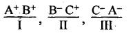
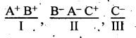
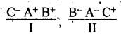
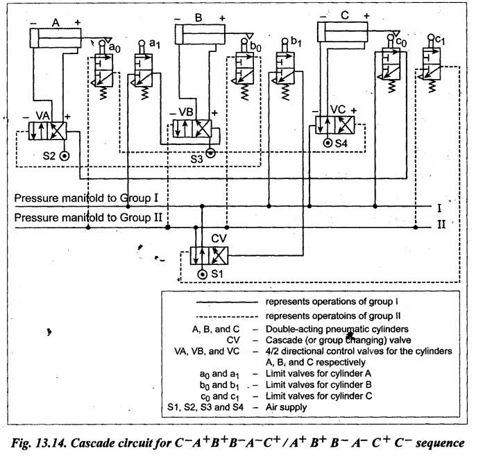
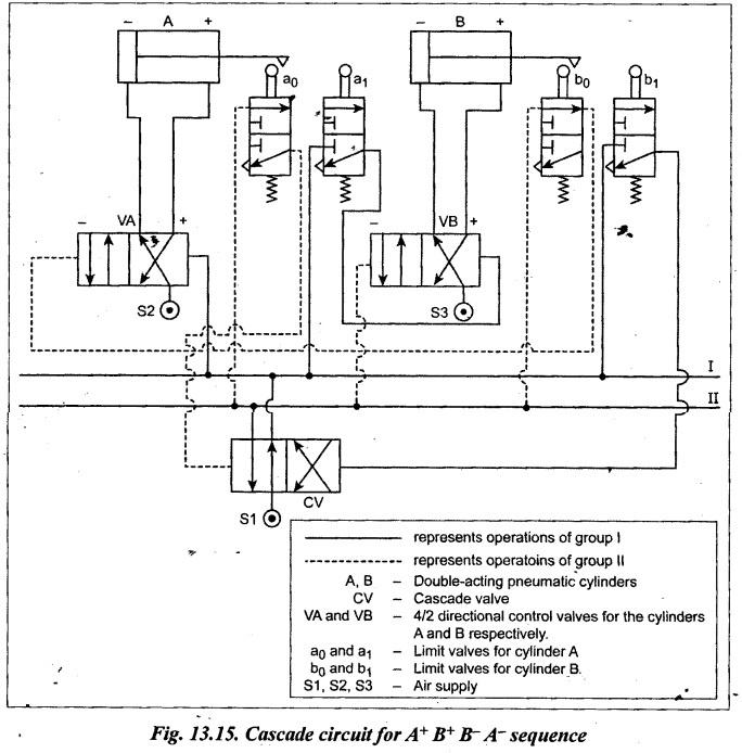
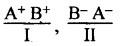
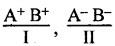
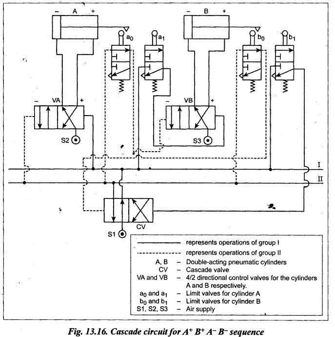
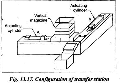
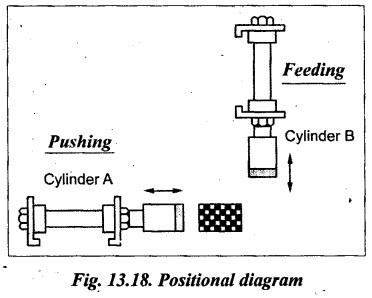
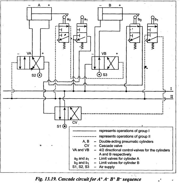
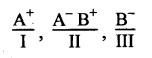
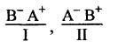
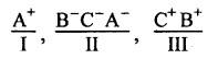
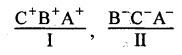
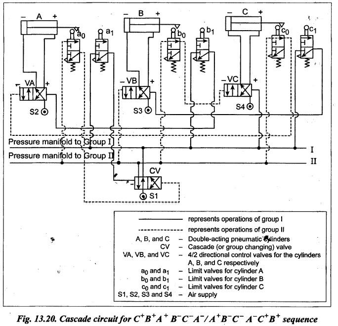
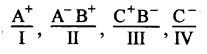
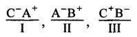
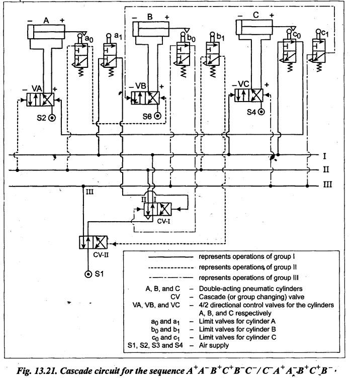
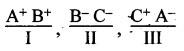
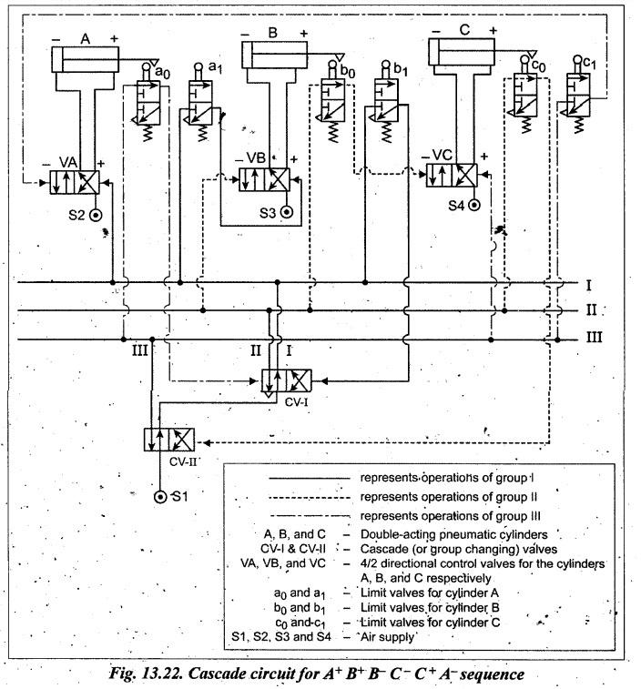
DESIGN OF MULTI ACTUATOR CIRCUITS Multi-cylinder pneumatic circuits can be designed in various methods. The five methods commonly used by engineers for the design of multi-cylinder pneumatic circuits are: 1. Cascade method, 2. Classic or intuitive method, 3. Step-counter method, 4. Karnaugh-Veitch (K-V) mapping method, and 5. Combinational circuit design. However, the design of multi-cylinder pneumatic circuits using cascade method is more important from our subject point of view. The cascade method is found to be the simplest and easiest method of designing multi- cylinder pneumatic circuits. 1. Procedure The following step by step procedure may be followed while using the cascade method. Step 1: Each cylinders are given, for convenience, individual letters (say A, B, C, etc.). The given sequence is written first with '+' representing extension (forward) stroke of the cylinder and '-' representing retraction (return) stroke of the cylinder (For example A+, B+, A-, B-, etc.) Step 2: The given sequence is split into minimum number of groups. The grouping can be done as below: (i) The first group is split where the change in stroke occurs. (ii) The second, third and subsequent groups are formed such that maximum of one change occurs within the group. (iii) No letter should be repeated within any group. (iv) The groups are identified by letters like I, II, III, etc. Illustration: Let us assume the sequence A+ B+ B- C+ C- A-. This sequence can be splitted into three groups as shown below: Step 3: Each group is assigned a pressure manifold line which must be pressurised only during the time the particular group is active. ⸫ Number of pressure lines = Number of groups Step 4: Selection of valves: (i) Each cylinder is provided with a pilot operated 4/2 DC valve. ⸫ Number of pilot control valves = Number of cylinders (ii) Limit valves are positioned at either end actuated by the piston rod to identify the extension and retraction of cylinders. The limit valves are denoted by a0, a1, bo, b1, etc., where the suffix '0' corresponds to valves which are actuated at the end of return stroke and the suffix '1' corresponds to valves which are actuated at the end of forward stroke. Each cylinder requires two limit valves. ⸫ Number of limit valves = 2 × Number of cylinders Each manifold line supplies air pressure to those limit valves within its particular group. (iii) In order to pressurize the various manifold lines in the proper order, one or more group changing valves or cascade valves are used. ⸫ Number of cascade (or group changing) valves = Number of groups – 1 Step 5: The valve connections are made as follows: (i) The output of each limit valve is connected to the pilot input corresponding to the next sequence step. (ii) The limit valve corresponding to the last step of the given group is 'not' connected to the pilot actuation of the DC valve of next cylinder. Instead, it is connected to the pilot line of the group changing or cascade valve so as to pressurize the manifold of the subsequent group. This manifold line is then connected to the pilot line corresponding to the first step of the next group. 1. Circuit design, drawing and checking can be accomplished very quickly. 2. Fault diagnosis and trouble-shooting are very simple. 3. Required task by each cylinder and their signal elements is fully ensured. 4. This avoids a problem that may occur because of air becoming trapped in the pressure line to control a valve and so preventing the valve from switching. Example 13.1 Three pneumatic cylinders A, B, and C are used in an automatic sequence of operation. A cylinder extends, B cylinder extends, B cylinder retracts and then A cylinder retracts, C cylinder extends and C cylinder retracts. Develop pneumatic circuits by cascade method. [OR] Design a pneumatic circuit for the following sequence using cascade method: A+B+B-A-C+C ̄. [OR] Design and draw a sequential circuit for the operation of C-A+B+B ̄A ̄C+ using cascade method. Solution: The steps involving during the design of this circuit is explained as below: Step 1: Given sequence is A+B+B-A-C+C ̄ Step 2: The given sequence can be initially splitted into three groups as In order to keep the number of groups minimal, the C- can be assigned to group I. So the ideal grouping is as follows: Step 3: Number of pressure lines = Number of groups = 2 Step 4: Selection of valves: (i) Number of pilot operated 4/2 DC valve = Number of cylinders = 3 Thus three cylinder actuation-VA, VB, VC—are provided. (ii) Number of limit valves = 2 × Number of cylinders = 2 × 3 = 6 Thus six limit valves - a0, a1, b0, b1, co, c1 - are provided. (iii) Number of cascade (or group changing) valves = {Number of groups} -1 = 2 - 1 = 1. So for this circuit, only one cascade valve is sufficient. Step 5: The valve connections are made as follows: (i). The cascade valve CV is shifted to its left envelop flow path configuration so that the pressure manifold to group I is pressurized. First line I is connected directly to the pilot line (-) of 4/2 DC valve VC. So retraction of C (C-) starts when group I is pressurized. At the end of retraction of C, the limit valve c0 is actuated. Now the pressure from manifold line I passes through c0 to the pilot line (+) of 4/2 DC vale VA. As a result, cylinder A extends (A+) and actuates limit valve a1. Pressure then passes from manifold line I through a to the pilot line (+) of 4/2 DC valve VB; this causes cylinder B to extend (B+) and actuates limit valve b1. Thus the sequencing of Group I is completed. (ii) Pressure manifold : Now the pressure line should be shifted from Group I to Group II. The pressure from limit valve b1 shifts the cascade valve CV to its right envelope flow path configuration and thus the pressure manifold II is pressurised. Line II is connected directly to the pilot line (−) of 4/2 DC valve VB. So retraction of B (B-) starts when a group II is pressurized. At the end of retraction of B, the limit valve b0 is actuated. Now, the pressure from manifold line II pass through limit valve b0 to the pilot line (-) of 4/2 DC valve VA. As a result, cylinder A retracts (A-) and actuates limit valve a0. Pressure then passes from manifold line II through limit valve a。 to the pilot line (+) of 4/2 DC valve VC; this causes cylinder C to extend (C+) and actuates limit valve c1. (iii) Now the pressure from limit valve c1 shifts the cascade valve CV to its left envelop flow path configuration and thus the pressure manifold I is pressurised again. Thus the automating sequencing of C-A+B+B-A-C+ can be achieved. The cascade circuit for the above A+B+B-A-C+C ̄ sequencing is drawn as shown in Fig. 13.14. Example 13.2 Design an electropneumatic circuit by cascade method for the following punching press application: Cylinder A is used to clamp the workpiece; Cylinder B is used for punching; and cylinder C removes the workpiece from the station. Solution: For the given problem, the operation sequence can be written as below : Cylinder A extends to clamp the workpiece (A+). Cylinder B extends to do the punching (B+). Cylinder B retracts after punching (B−). Cylinder A retracts to unclamp the workpiece (A ̄). Cylinder C extends to remove the workpiece (C+). Cylinder C retracts after removal of workpiece (C−). Thus the sequence for this case is A+ B+ B- A-C+ C-. Now the solution to this sequence is exactly the same as that of Example 13.1. Fig.13.14 is the required sequential circuit. Example 13.3 Develop an electropneumatic circuit by cascade method for the following sequence : A+B+B ̄A ̄ where A and B stand for cylinders, (+) indicates extension and (-) retraction of cylinders. Solution: The solution to this design problem is very much similar to that of the previous problem. So the same procedure may also be followed for this problem. Step 1 : Given sequence: A+ B+ B- A- Step 2: Grouping ; Step 3: Number of pressure lines = Number of groups = 2 Step 4: (i) Number of pilot operated 4/2 DC valve = Number of cylinders = 2 (ii) Number of limit valves = 2 × Number of cylinders = 2 × 2 = 4 (iii) Number of cascade valves = Number of groups – 1 = 2 – 1 = 1 Step 5: The cascade circuit for the sequence A+ B+ B- A- is drawn as shown in Fig.13.15. Example 13.4 Design and explain the fluid power circuit for a drilling machine to discuss the following functions : (i) Clamping the workpiece, (ii) Drilling the workpiece, and (iii) Unclamping the workpiece. Solution: Let us use two cylinders A and B for clamping and drilling operations respectively. The operation sequence is as follows: Cylinder A extends to clamp the workpiece (A+). Cylinder Bextends to do the drilling (B+). Cylinder B retracts after drilling (B-). Cylinder A reacts after to unclamp the workpiece (A-). So the sequence is A+B+B-A-. Now the solution to this sequence is exactly the same as that of Example 13.3. Fig.13.15 for is the required circuit. Example 13.5 Develop an electropneumatic circuit for the following sequence A+B+A-B- where A and B stand for cylinders, (+) indicates extension and (−) retraction of cylinders. Solution: Step 1: Given sequence : A+B+A-B- Step 2: Grouping : Step 3: Number of pressure lines = Number of groups = 2 Step 4: (i) Number of pilot operated 4/2 DC valve = Number of cylinders = 2 (ii) Number of limit valves = 2 × Number of cylinders = 2 × 2 = 4 (iii) Number of cascade valves = Number of groups – 1 = 2 - 1 = 1 Step 5: The cascade circuit for the sequence A+B+A-B- is drawn as shown in Fig. 13.16. Example 13.6 Two pneumatic cylinders are used to transfer parts from a magazine onto a chute (Fig.13.17). When a push-button is pressed, cylinder A extends, pushing the part from the magazine and positions it in preparation for transfer by cylinder B onto the outfeed chute. Once the part is transferred, the cylinder A retracts, followed by the cylinder B. Design and draw a sequential circuit for the above operation using cascade method. Solution: First let us identify the sequence of operations before applying the cascade method. Step 0: Write the statement of the problem The positional layout of the two cylinders are depicted in Fig.13.18. Let A be the first cylinder (pushing) and B be second cylinder (feeding) as shown in Fig.13.18. First cylinder A extends and brings under stamping station where cylinder B is located. Cylinder B then extends and stamps the job. Cylinder A can return back only when cylinder B has retracted fully. Let us represent the control task using notational form as below: Cylinder A advancing step is designated as A+ Cylinder A retracting step is designated as A- Cylinder. B advancing step is designated as B+ Cylinder B retracting step is designated as B ̄ Therefore, given sequence for clamping and stamping is A+B+A ̄B ̄. Now, the solution to this sequence is exactly the same as that of Example 13.5. Fig.13.16 is the required sequential circuit. Example 13.7 Design an electro pneumatic circuit for the following sequence: A+A ̄B+B ̄, where + is extension and – is retraction. Solution: Step 1: Given sequence: A+A-B+B- Step 2: Grouping: The given sequence can be initially split into three groups as In order to keep the number of groups minimal, the B- can be assigned to group I. So the ideal grouping is as follows: Step 3: Number of pressure lines = Number of groups = 2 Step 4: (i) Number of pilot operated 4/2 DC valve = Number of cylinders = 2 (ii) Number of limit valves = 2 × Number of cylinders = 2 × 2 = 4 (iii) Number of cascade valves = Number of groups – 1 = 2 – 1 = 1 Step 5: The cascade circuit and their valve connections for the sequence A+A-B+B ̄ is drawn as shown in Fig.13.19. Example 13.8 Three pneumatic cylinders A, B, C are used in an automatic sequence of operation. A cylinder extends, B cylinder retracts, C cylinder retracts and then A cylinder retracts, C cylinder extends and B cylinder extends. Develop pneumatic circuits by cascade method. Solution: Step 1: For the given data, the operation sequence is A+B ̄C A ̄C+B+. Step 2: Grouping: The given sequence can be initially split into three groups as In order to keep the number of groups minimal, the BTM can be assigned to group I. So the ideal grouping is as follows: Step 3: Number of pressure lines = Number of groups = 2 Step 4: (i) Number of pilot operated 4/2 DC valve = Number of cylinders = 3 (ii) Number of limit valves = 2 × Number of cylinders = 2 × 3 = 6 (iii) Number of cascade valves = Number of groups – 1 = 2 − 1 = 1 Step 5: The cascade circuit for the sequence C+B+A+B- C-A- is drawn as shown in Fig.13.20. Example 13.9 Draw a sequential pneumatic circuits for the following sequence A+A ̄ ̄B+C+B ̄ ̄C ̄ using cascade method. Solution: Step 1: Operation sequence: A+A ̄B+C+B ̄C ̄ Step 2: Grouping: The given sequence can be initially split into three groups as In order to keep the number of groups minimal, the C- can be assigned to group I. So the ideal grouping is as follows: Step 3: Number of pressure lines = Number of groups = 3 Step 4: (i) Number of pilot operated 4/2 DC valve = Number of cylinders = 3 (ii) Number of limit valves = 2 × Number of cylinders = 2 × 3 = 6 (iii) Number of cascade valves = Number of groups – 1= 3 – 1 = 2 Step 5: The cascade circuit for the sequence A+A-B+C+B-C- is drawn as shown in Fig.13.21 Example 13.10 Design an electropneumatic circuit using cascade method for the following sequence A+B+ B- C- C+ A-, where A, B and C stand for cylinders, (+) indicates extension and (--) retraction of cylinders. Solution: Step 1: Given sequence: A+ B+ B- C-C+ A- Step 2: Grouping: Step 3: Number of pressure lines = Number of groups = 3 Step 4: (i) Number of pilot operated 4/2 DC valve = Number of cylinders = 3 (ii) Number of limit valves = 2 × Number of cylinders = 2 × 3 = 6 (iii) Number of cascade valves = Number of groups -1 = 3 – 1 = 2 Step 5: The cascade circuit and for the sequence A+B+ B- C-C+ A- is drawn as shown in Fig. 13.22.1. Cascade Method of Pneumatic Circuit Design
2. Advantages of Gascade Method
Hydraulics and Pneumatics: Unit IV: Pneumatic and Electro Pneumatic Systems : Tag: : Pneumatic and Electro Pneumatic Systems - Hydraulics and Pneumatics - design of multi actuator circuits
Related Topics
Related Subjects

Hydraulics and Pneumatics
ME3492 4th semester Mechanical Dept | 2021 Regulation | 4th Semester Mechanical Dept 2021 Regulation