Theory of Machines: Unit I: Kinematics of Mechanisms
cycloidal follower motion
Kinematics of Mechanisms - Theory of Machines
In this case, as its name suggests, the displacement diagram of the follower is generated from a cycloid.
CYCLOIDAL FOLLOWER MOTION
• In
this case, as its name suggests, the displacement diagram of the follower is
generated from a cycloid.
• We
know that cycloid is a locus of a point on a circle rolling on a straight line.
• In
case of cams, this straight line is the lift of the follower (L) and the
circumference of the rolling circle is equal to the lift of the follower. The
radius of the circle will be L/2π.
• The
cycloidal curve is considered the best of all cam contours, as it has the
lowest vibration, surface wear, contact stress, noise, and shock.
• Thus
the cycloidal motion is recommended for follower when cam rotates even at
higher speeds (i.e., it can be used for low, medium or higher speeds).
1. Construction of Displacement Diagram
The
displacement diagram when the follower moves with cycloidal motion is shown in
Fig.3.20.
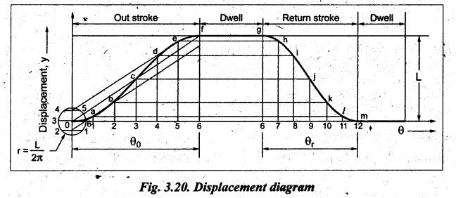
The
displacement diagram can be constructed as follows:
Step 1:
Divide the angular displacement of the cam outstroke into any even number of
equal parts (say 6) and draw vertical lines through these points.
Step 2:
Draw diagonal line ‘0ƒ”.
Step 3:
Draw circle with centre 0 with radius equal to (L/2π).
Step 4:
Divide the circle into same number of equal parts (say 6) as cam displacement
is divided.
Step 5:
Project the points on the circles to its vertical diameter and these points on
the diameter are projected parallel to the diagonal (0f) to the
corresponding vertical lines 1, 2, 3, 4, 5 and 6. Now obtain the intersection
points a, b, c, d, e and f.
Step 6:
Join these intersection points to obtain the cycloidal displacement curve for
the outstroke of the follower.
Step 7:
Follow the same procedure to draw the displacement curve for the return stroke
of the follower.
2. Determination of Displacement, Velocity, Acceleration and Jerk of Follower having Cycloidal Motion
1. Displacement of the Follower
Mathematically,
the displacement equation for the follower having cycloidal motion during
outstroke is given by
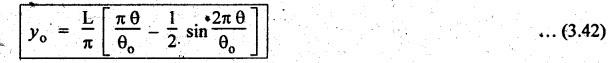
where
yo
= Displacement of the follower during outstroke after any time i,
L=
Lift (or stroke) of the follower,
θ
= Angle through which the cam rotates in time t, and
θo
= Outward angle (or angle of ascent).
Similarly,
the displacement of follower during return stroke,
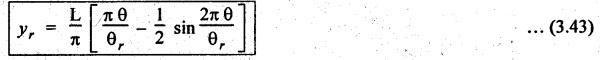
where
θr
= Return angle (or angle of descent)
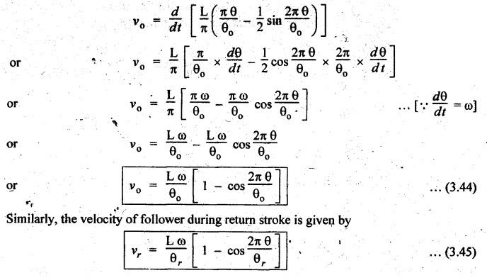
(ii) Velocity of the Follower
We
know that, Velocity = Rate of change of displacement with respect to time
v
= dy/dt
Velocity
of follower during outstroke is given by
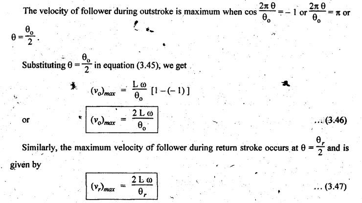
Maximum
velocity of follower during outward and return strokes
(iii) Acceleration of the Follower
We
know that, Acceleration = Rate of change of velocity with respect to time
a
= dv/ dt
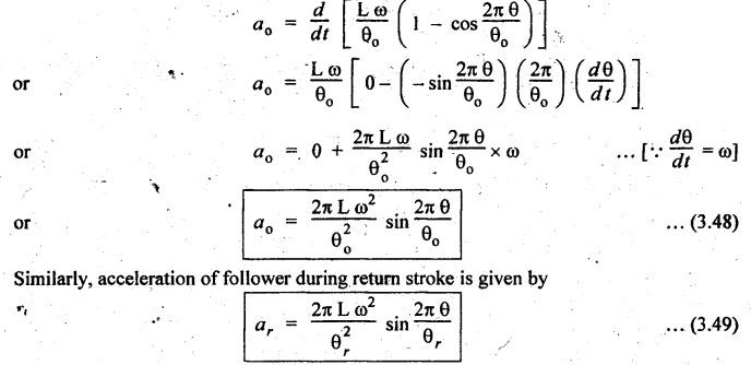
Acceleration
of follower during outstroke is given by
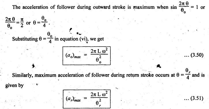
Maximum
acceleration of follower during outward and return strokes
(iv) Jerk of the Follower
We
know that,
Jerk
= Rate of change of acceleration with respect to time
j
= da / dt
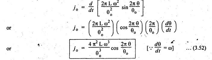
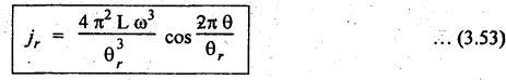
Jerk
of follower during outward stroke is given by
Similarly,
jerk of follower during return stroke is given by
Maximum
jerk of follower during outward and return strokes
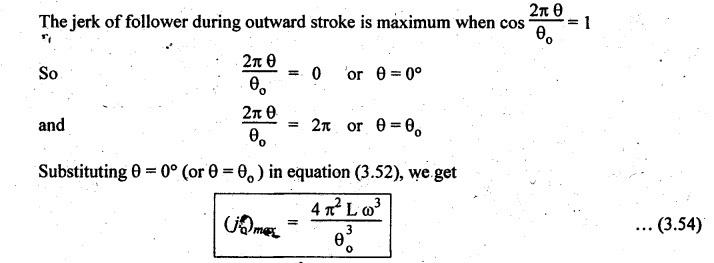
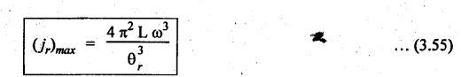
Similarly,
the maximum jerk of follower during return stroke occurs when θ
= 0° and θ =
θr
and is given by
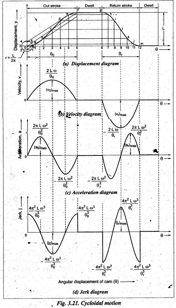
• Fig.3.21
illustrates the displacement, velocity, acceleration and jerk diagrams when the
follower moves with cycloidal motion.
•
From Fig.3.21, the following points may be observed:
■
The velocity of the follower is zero at the beginning and at the end of its
strokes and increases gradually to a maximum at mid-stroke.
■
The acceleration of the follower is zero at the beginning, mid and at the end
of stroke and is maximum at 1/4th and 3/4th of each stroke.
■
The jerk of the follower is zero at 1/4th and 3/4th of its stroke and is
maximum at the beginning, mid and at the end of stroke.
■
Since the acceleration curve is continuous and the value of jerk is not
infinite anywhere, therefore the cycloidal curve is considered the best of all
cam contours. Hence the cams with cycloidal motion for followers are
recommended for higher speeds, (i.e., this type of follower motion is
suitable for lower, moderate and higher speed applications).
Theory of Machines: Unit I: Kinematics of Mechanisms : Tag: : Kinematics of Mechanisms - Theory of Machines - cycloidal follower motion
Related Topics
Related Subjects

Theory of Machines
ME3491 4th semester Mechanical Dept | 2021 Regulation | 4th Semester Mechanical Dept 2021 Regulation