Engineering Mechanics: Unit I: Statics of Particles
Concurrent Force System in Three Dimensions
with Solved Example Problems
In most of the real life problems and engineering applications, three dimensional force systems are involved.
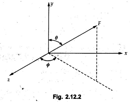
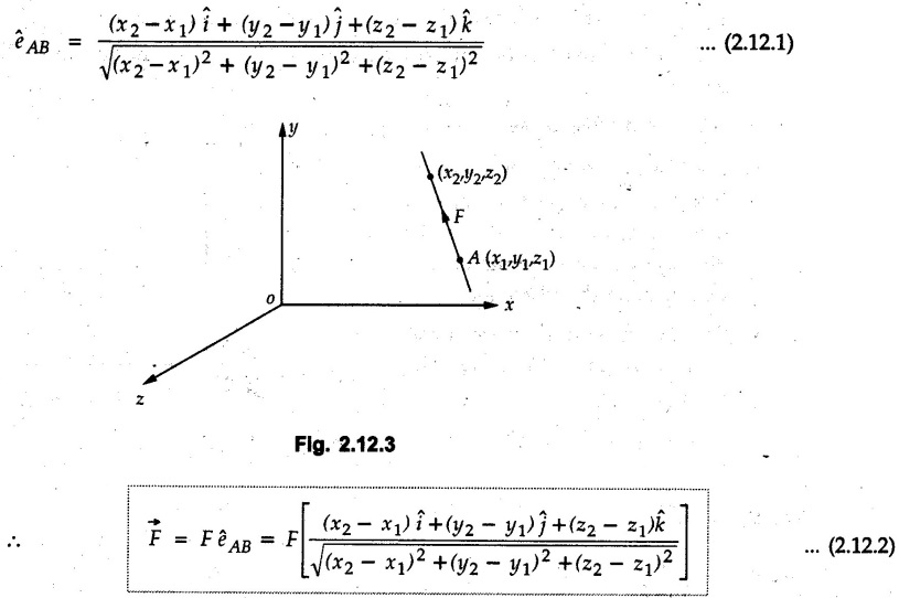
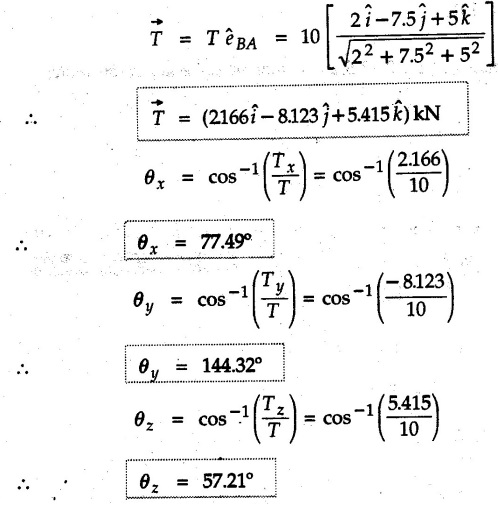
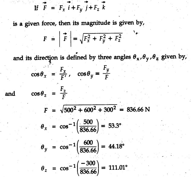
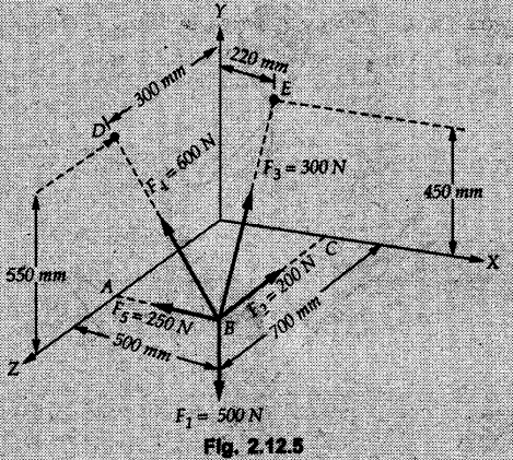
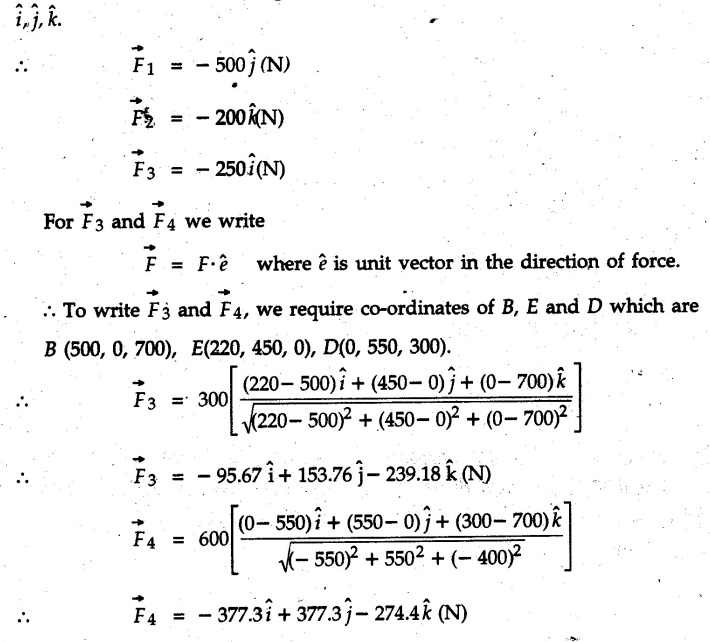
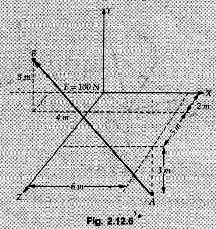
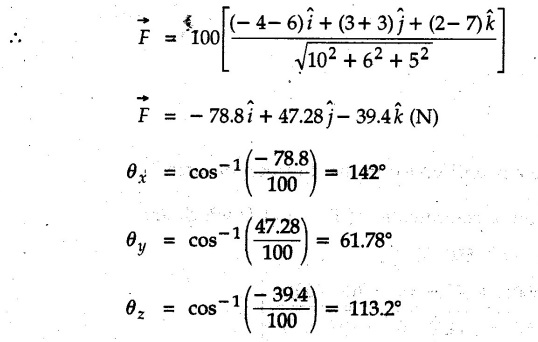
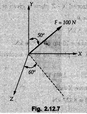
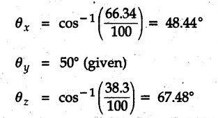
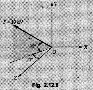
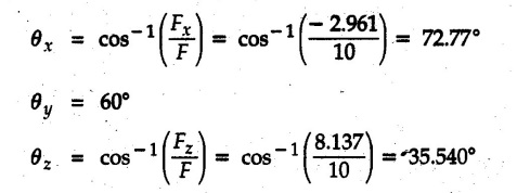
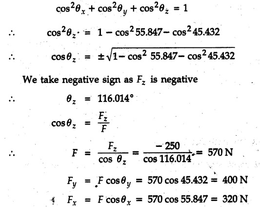
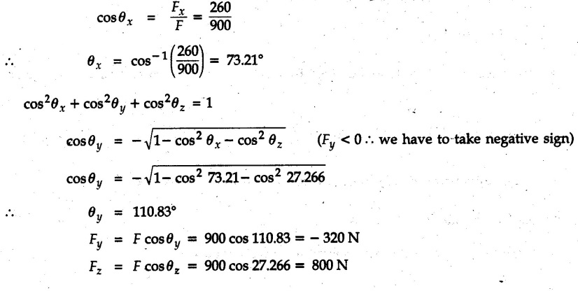
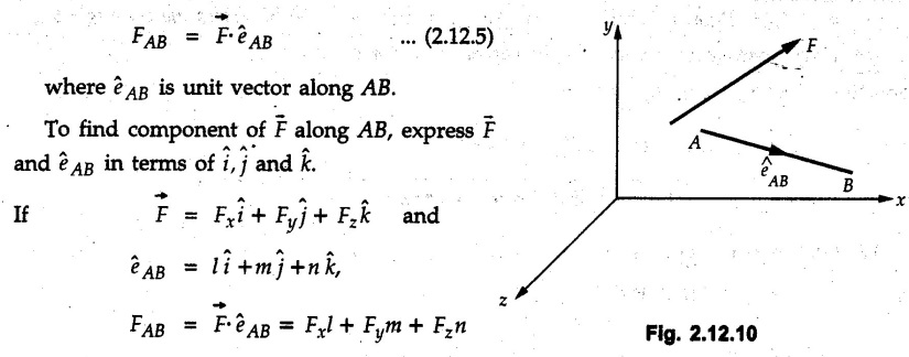
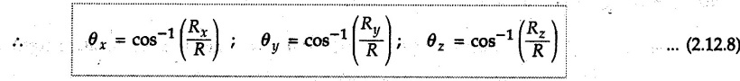
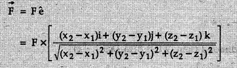
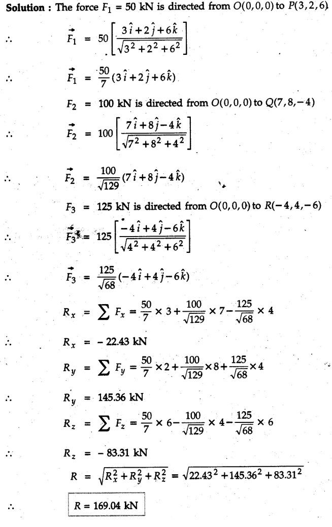
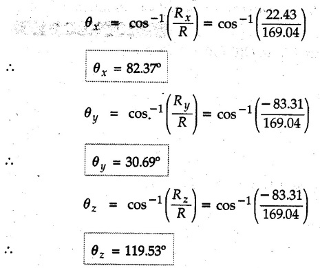
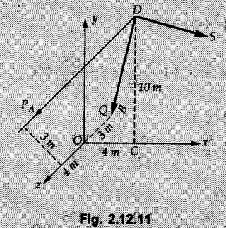
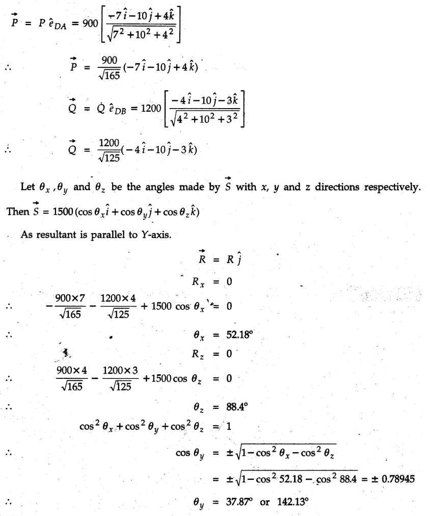
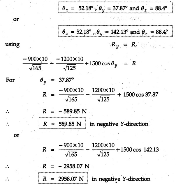
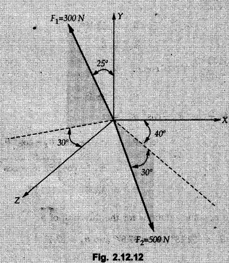
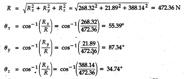
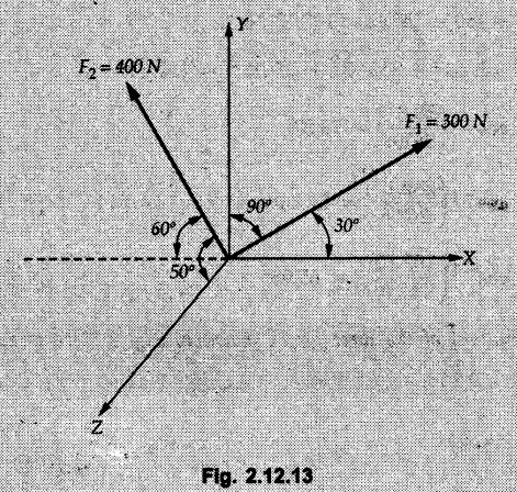
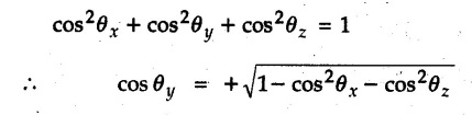
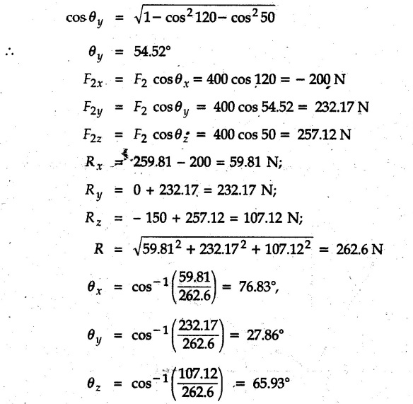
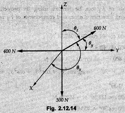
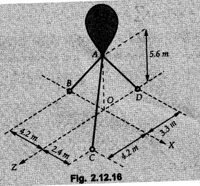
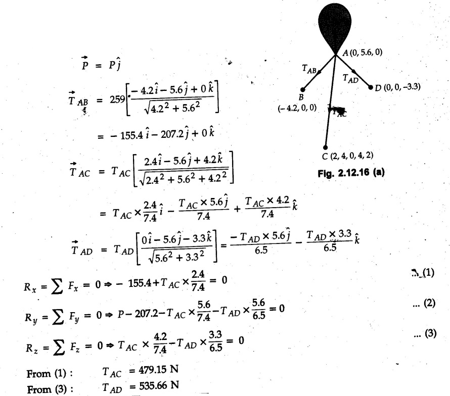
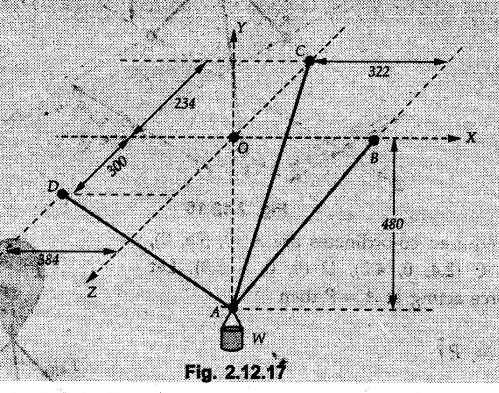
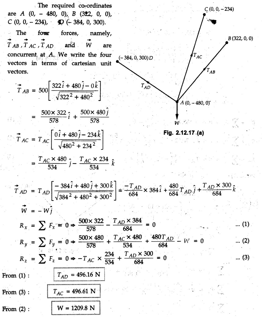
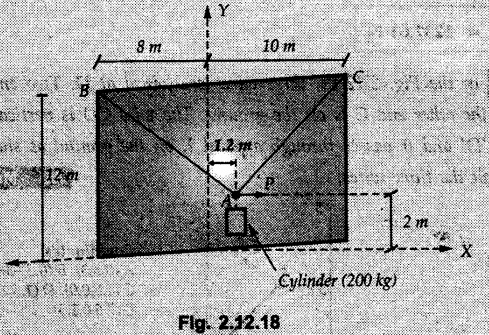
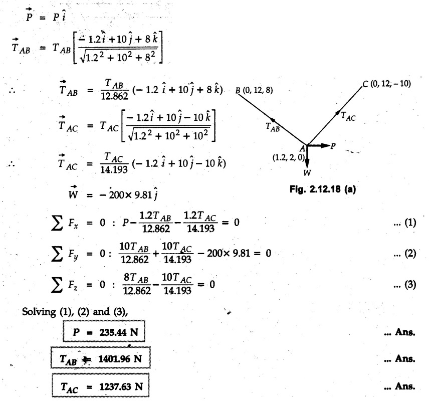
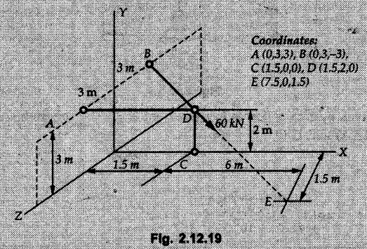
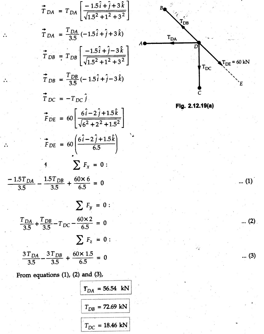
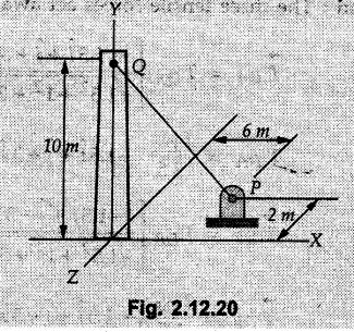
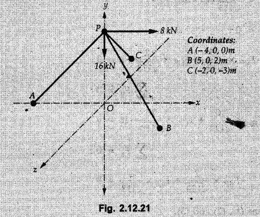
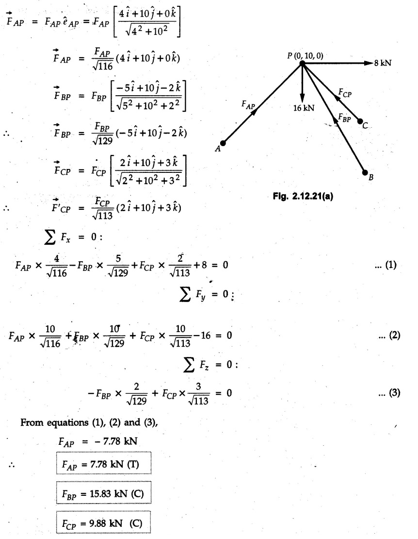
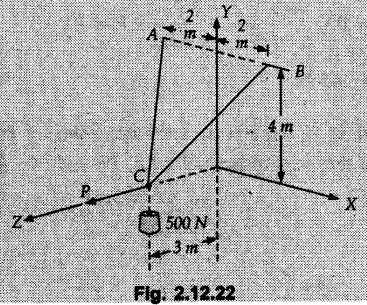
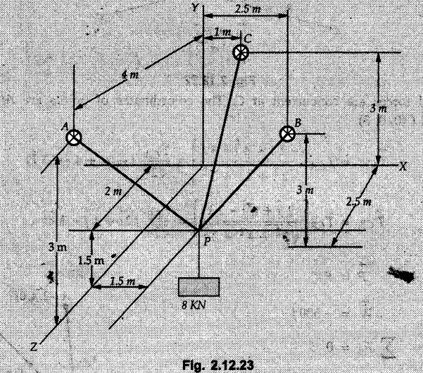
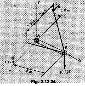
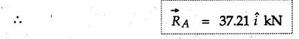
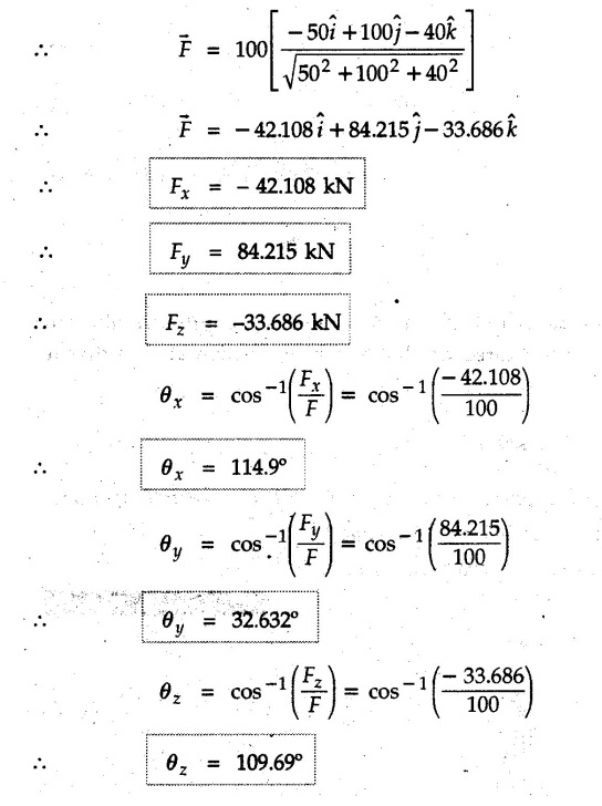
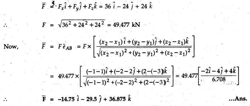
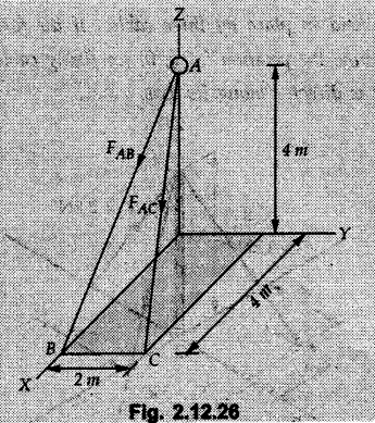
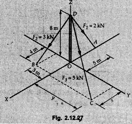
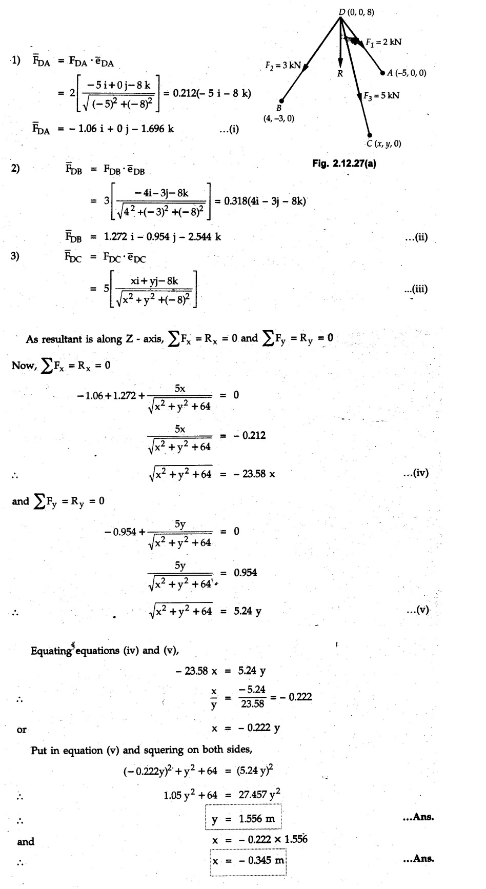
Concurrent Force System in Three Dimensions • In most of the real life problems and engineering applications, three dimensional force systems are involved. • In such cases, the forces have to be expressed in terms of unit vectors along three mutually perpendicular x, y and z directions. • This enables us to then get scalar equations or perform vector operations like scalar product, vector product etc. 1. Force as a Vector in Three Dimensions • The procedure for expressing a force in terms of unit vectors î, ĵ and î along x, y and z directions can be categorized into four types depending upon the available data. • We now discuss these 4 types. 1. Forces parallel to x, y or z axis : • If a force is parallel to one of the coordinate axes, it can be directly written in terms of unit vector along that direction. • For example, the three forces shown in Fig. 2.12.1 can be written as 2. Angle made by force with one of the axes is given and the angle made by its projection in a plane with one of the axis in that plane is given : • Resolve the force into two mutually perpendicular components: i) A component along the axis with which angle of force is given and ii) The perpendicular component which is the projection of force in the plane of the other two axes. • Then resolve the projection along the two axes in the plane of the projection. • For the force shown in Fig. 2.12.2, Fy = F cos θ and projection in x-z plane is F sin θ. • Resolving the projection in x and z directions, we get Fx = F sin θ sin ϕ Fz = F sin θ cos ϕ 3. Two points on the line of action of force are known : • If a force of magnitude F is directed from point A (x1, y1, z1) to B (x2, y2, z2), then the unit vector from A to B is 4. Direction cosines of the force are known : • If θx, θy and θz are the angles made by the force with x, y and z – directions respectively, then cos θx, cos θy and cos θz are called the direction cosines. • The components of force can be obtained using Fx = F cosex Fx = F cos θx Fy = F cos θy Fz = F cos θz • The relation between these direction cosines is directions • The angles θx, θy and θz lie between 0° and 180°. • If components Fx, Fy and Fz of force F are known in three dimensions, its magnitude and. direction (defined by the three angles θx, θy, θz) can be obtained using Example 2.12.1 A force Solution : Example 2.12.2 A force of magnitude 500 N is passing through the origin and a point A (0.2, 1, 0) m. Write the vector form of the force. Solution : Example 2.12.3 Find the unit vector of the force Solution : Example 2.12.4 What is the inclination of a force with respect to the x axis if it is inclined at 60° with Y-axis and 30° with the Z-axis ? Solution : Example 2.12.5 The tension in the supporting cable AB is 10 kN as shown in Fig. 2.12.4. Write the force which the cable exerts on the beam BC as a vector Solution: The co-ordinates of A and B are: A (2, 0, 5) and B (0, 7.5, 0) Example 2.12.6 Determine the magnitude and direction of the force Solution: Example 2.12.7 Express the 5 forces shown in Fig. 2.12.5 as vectors in cartesian co-ordinates system. Solution : Forces which are parallel to X, Y or Z axes can be written directly in terms of Example 2.12.8 Express the 100 N force F shown in Fig. 2.12.6 as a vector in cartesian co-ordinate system and find its angles with X, Y and Z axes. Solution: The co-ordinates of A and B are A (6, 3, 7) and B (- 4, 3, 2). Example 2.12.9 Determine the X, Y and Z components of the 100 N force shown in Fig. 2.12.7. Also find the angles with the three co-ordinate axes. (See Fig. 2.12.7 on next page) Solution : As angle with Y-axis is 50°, Fy = 100 cos 50° = 64.28 N The components in X - Z plane will be 100 sin 50, which we have to resolve along X and Z direction. As angle with Z axis is 60o, Fz = (100 sin 50) × cos 60 Fz = 38.3 N and Fx = (100 sin 50) × sin 60 Fx = 66.34 N Example 2.12.10 Determine the X, Y and Z components of the 10 kN force shown in Fig. 2.12.8 and the angles with the three co-ordinate axes. Solution: Angle with the horizontal X - Z plane is given as 30°. ⸫ Angle with Y - axis = 60° = θy ⸫ Fy = 10 cos 60 = 5 kN The component in X- Z plane = 10 sin 60 = 8.66 kN This 5 kN component in X - Z plane has to be resolved in X and Z directions and angle with Z direction is 20°. ⸫ Fx = 8.66 sin 20 = 2.961 kN (X-components is on negative X-axis) Fz = 8.66 cos 20 = 8.137 kN Example 2.12.11 Determine the X, Y, Z components of the 500 N force shown in Fig. 2.12.9. Solution : θx = 65°, θy = 70° θz = 180 - 32.86 = 147.14 (θz is angle with positive Z-axis) Fx = F cos θx = 500 cos 65 = 211.31 N Fy = F cos θy = 500 cos 70 = 171 N Fz = F cos θz = 500 cos 147.14 = -420 N Example 2.12.12 A force acting at the origin of coordinate system has θx = 55.847° and θy = 45.432°. Knowing that the Z component of force is - 250 N, determine the angle θy, the other components of force and the magnitude of force. Solution: Example 2.12.13 A force F = 900 N acts at the origin of a coordinate system. If Fx = 260 N, θz = 27.266° and Fy < 0. Determine Fy, Fz, θx, and θy. Solution : 2. Component or Projection of Force on a Line Other than the Co-ordinate Axes The component or projection of force F on a line AB is 3. Concurrent Force System without Couple • The resultant of concurrent force system is a force acting through the point of concurrence of the given forces. • The x, y and z components of resultant can be obtained using • Magnitude of resultant can be obtained using • The direction of resultant is defined by the three angles with coordinate axes given by • These three equations can be solved for three unknowns. Note: • To resolve any force along x, y, z axis apply Where, x1, y1, z1 = Coordinates of initial point. x1, y1, z1 = Coordinates of final point. Example 2.12.14 Determine the resultant of the three concurrent forces Solution: Example 2.12.15 Forces 32 kN, 24 kN, 24 kN and 120 kN are concurrent at origin and are respectively directed through the points whose coordinates are A(2,1,6), B(4,- 2,5), C(-3,-2,1) and D(5,1,-2). Determine the magnitude of the resultant and the angles it makes with coordinate axes. Solution: F1 = 32 kN is directed from O(0,0,0) to A(2,1,6) F3 = 24 kN is directed from O(0,0,0) to C(-3,-2,1) F4 = 120 kN is directed from O(0,0,0) to D(5,1,-2) Example 2.12.16 A system of concurrent forces 50 kN, 100 kN and 125 kN act at a point O(0,0,0) and the forces are directed respectively through the points whose coordinates are P (3, 2, 6), Q (7, 8, 4) and R ( 4, 4, 6). Determine resultant and its direction. Solution: The direction of the resultant is defined by the three angles θx, θy and θz with the X, Y and Z axes respectively. Example 2.12.17 Three forces P = 900 N, Q = 1200 N and S = 1500 N act at a point O as shown in Fig. 2.12.11. The force P acts along the line DA, while Q acts along the line DB. Determine the direction of force S, so that the resultant of the three forces is parallel to Y-axis. What is the magnitude of the resultant force? Solution: The co-ordinates of points are as follows: D (4, 10, 0), A (− 3, 0, 4), B(0, 0, – 3) Thus there are two possible solutions for the direction of Example 2.12.18 Find the magnitude and direction of resultant of the two forces shown in Fig. 2.12.12. Solution: The X, Y and Z components of the two forces are F1x = 300 sin 25 sin 30 = – 63.39 N F1y = 300 cos 25 = 271.89 N F1z = 300 sin 25 cos 30 = 109.8 N F2x = 500 cos 30 cos 40 = 331.71 N F2y = - 500 sin 30 = - 250 N F2z = 500 cos 30 sin 40 = 278.34 N Rx = F1x + F2x = -63.39 + 331.71 = 268.32 N Ry = Fly + F2y = 271.89 - 250 = 21.89 N Rz = F1z + F2z = 109.8 + 278.34 = 388.14 N Example 2.12.19 Find the magnitude and direction of resultant of the two forces shown in Fig. 2.12.13. Solution: F1 = 300 N makes 90° angle with Y-axis. Hence it lies in X-Z plane. As it makes 30° angle with X axis, it will make 60° angle with negative Z-axis. ⸫ F1x = 300 cos 30 = 259.81 N Fly = 0 F1z = - 300 sin 30 = - 150 N For F2 = 400 N, θx = 180 - 60 = 120°, θz = 50°. (take positive sign as y component is positive) Example 2.12.20 Resultant of the three forces shown in Fig. 2.12.14 is zero. Find values of θx, θy, and θz. Solution: As resultant is zero, Rx = 0, Ry = 0 and Rz = 0 Rx = 0 ⇒ 600 cos θx = 0 ⸫ θx = 90° Ry = 0 ⇒ 600 cos θy – 400 = 0 θy = 48.19° Rz = 0 ⇒ 600 cos θz -300 = 0 θz = 60° Example 2.12.21 Find the magnitude and direction of resultant of the three forces shown in Fig. 2.12.15. Solution: Components of F1 can be written using its projection on X components of F2 using direction cosines and components of F3 using unit vector in the direction of force. Flx = 400 cos 40 cos 20 = 287.94 N Fly = 400 sin 40 = 257.12 N F1z = - 400 cos 40 sin 20 = - 104.8 N Example 2.12.22 Three cables AB, AC and AD hold down a balloon as shown in Fig. 2.12.16. Find vertical force exerted at the base of balloon A, knowing that tension in cable AB is 239 N. Solution: The required co-ordinates are A B (- 4.2, 0, 0), C (2.4, 0, 4.2), D (0, 0, magnitude of force acting at A = P then Example 2.12.23 Three cables support a load W as shown in Fig. 2.12.17 knowing that tension in cable AB is 500 N, find W. What will be magnitudes of tensions in AC and AD? Solution: Example 2.12.24 A 200 kg cylinder is hung by means of two cables AB and AC which are attached to the top corners B and C of a vertical wall. A horizontal force P perpendicular to the wall holds the cylinder 1.2 m away from the wall. Determine the value of P and the tension in the cables AB and AC. Solution: The given system of forces is concurrent at A. The required co-ordinates are A (1.2, 2, 0), B (0, 12, 8) and C (0, 12, 10). Example 2.12.25 In the Fig. 2.12.19, three wires are joined at D. Two ends A and B are on the wall and the other end C is on the ground. The wire CD is vertical. A force of 60 KN is applied at 'D' and it passes through a point E on the ground as shown in figure. Find the forces in all the three wires. Solution: The three tensile forces act away from D. Example 2.12.26 A metal guy rope tied to a peg at P shown in Fig. 2.12.20 keeps an electric post in equilibrium. The force in the guy rope is 1.25 kN. Find the components of the force at P and the angles of inclination of the force with the three rectangular axes. Solution: The coordinates of P and Q are P(6,0,-2) and Q(0,10,0) The force F of magnitude 1.25 kN is directed from P and Q. Example 2.12.27 Two forces act upon a tripod at 'P' as shown in Fig. 2.12.21. The force 8 kN is parallel to x-axis and the force 16 kN is parallel to y-axis. Determine the forces acting at the legs of tripod if the legs rest on ground at A, B and C whose coordinates with respect to O are given. The height of the P above the origin is 10 m. Solution: The coordinates of P are (0, 10, 0). The two given forces can be written as The forces in the legs of the tripod are assumed to be compressive. Considering all forces acting at P, these forces will be directed towards P, Example 2.12.28 A load of 500 N is to be held in equilibrium by means of two strings CA and CB and by a force P as shown in Fig. 2.12.22. Determine tensions in strings and magnitude of P. Solution All forces are concurrent at C. The co-ordinates of points are A(-2, 4, 0), B(2, 4, 0) and C(0, 0, 3). Example 2.12.29 A weight of 8 kN is suspended by means of three cables as shown in Fig. 2.12.23. Determine the forces in the cables PA, PB and PC. Solution: The co-ordinates of points required to write forces in vector form are as follows: A(0, 3, 4), B(2.5, 3, 2.5), C(1, 3, 0), P(1.5, 1.5, 2) Consider forces acting at point P. The tensile forces act away from P. Example 2.12.30 Determine the tension in cables BC and BD and the reactions at the ball and socket at A for the rod shown in Fig. 2.12.24 Solution: The force in rod AB is compressive. The co-ordinates of points are B (5, 0, 0), C(0, 1.25, 1.5) and D(0, 1.5, – 2.5). The forces are concurrent at B. The reaction at A equals the force in rod AB. As this force is compressive, the force in rod at A is directed along negative x-direction due to which reaction at A is directed in positive x-direction. Example 2.12.31 The guy wire a pole is anchored by means of a bolt at a point P as shown 2.12.25. The force in the wire is 100 kN. Determine i) The components of the force in the x, y and z-directions and ii) The direction of the force. Solution: The force of 100 kN is directed from P (50, 0, 40) to Q (0, 100, 0). Example 2.12.32 The x, y, z, component of a force are 36 kN, −24 kN and 24 kN respectively. Find the component of this force along the line joining A (1, 2, -3) and B(-1, -2, 2) Solution: Example 2.12.33 The cable exerts forces FAB = 100 N and FAC = 120 N on the ring at A as shown in Fig. 2.12.26. Determine magnitude of the resultant force acting at A. Solution: The co-ordiantes of A, B and C are A(0, 0, 4), B(4, 0, 0) and C(4, 2, 0) FAB = 100 N is directed from A to B Example 2.12.34 A pole is held in place by three cables. If the force of each cable acting on the pole is shown, determine the position (x, y, 0) for fixing cable DC so that the resultant force exerted on the pole is directed along its axis. Solution : Fig. 2.12.27 (a) shows different forces acting on the pole.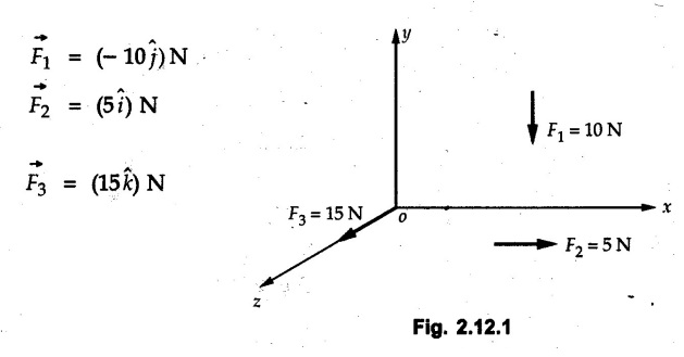

Solved Examples for Understanding
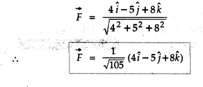
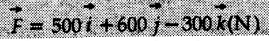
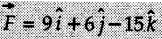 acts through the origin. What is the magnitude of the force and the angle it makes with X, Y, and Z axis?
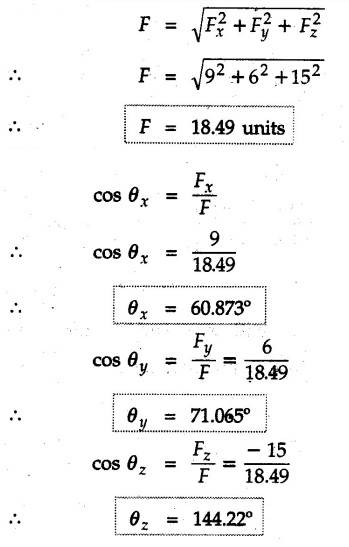
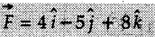
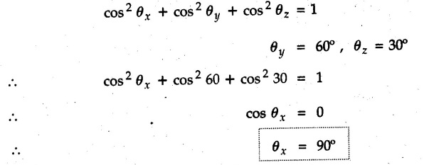
![]() . Determine the angles of
. Determine the angles of ![]() p forms with the positive x, y and z axis.
p forms with the positive x, y and z axis.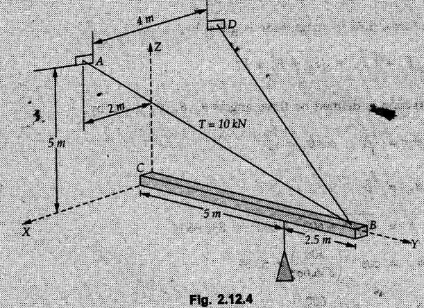


 • The conditions for equilibrium of a concurrent force system are
Solved Examples for Understanding
 The forces are in Newton.
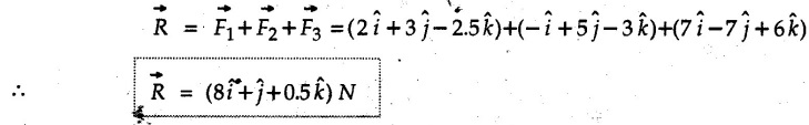

![]()


Engineering Mechanics: Unit I: Statics of Particles : Tag: : with Solved Example Problems - Concurrent Force System in Three Dimensions
Related Topics
Related Subjects

Engineering Mechanics
ME3351 3rd semester civil, Mechanical Dept | 2021 Regulation | 3rd Semester Mechanical Dept 2021 Regulation