Fluid Mechanics and Machinery: Unit 4: Turbines
Classification of Reaction Turbine
The important Reaction turbines are (i) Francis turbine (ii) Kaplan turbine (iii) Propeller turbine.
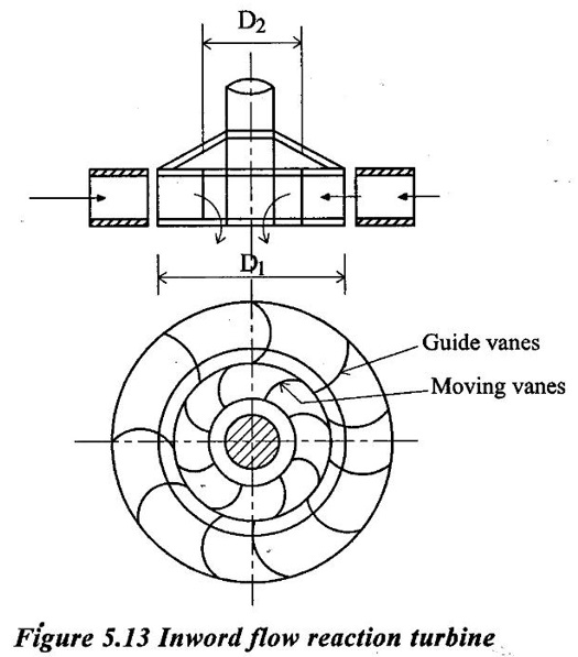
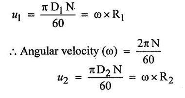
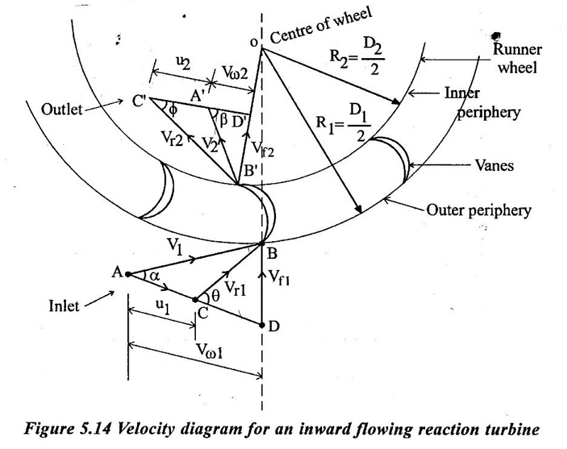
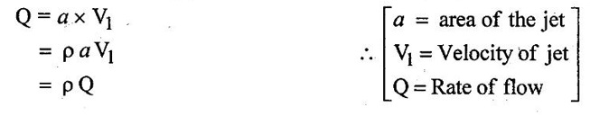
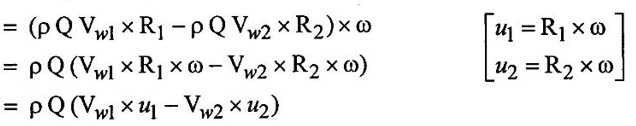
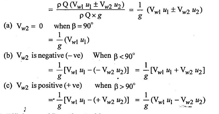
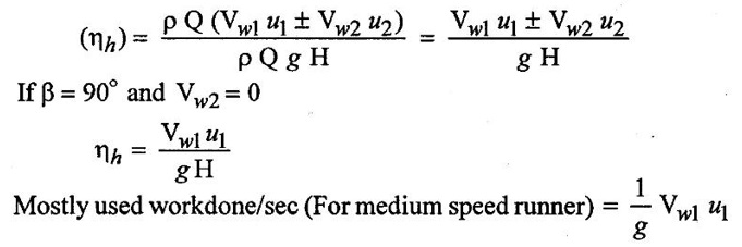
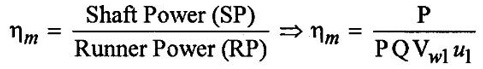
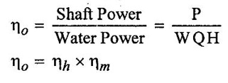
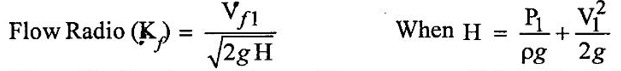
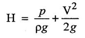
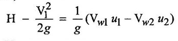
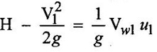
CLASSIFICATION OF REACTION TURBINE The important Reaction turbines are (i) Francis turbine (ii) Kaplan turbine (iii) Propeller turbine. Reaction Turbines may be classified into the following three types depending upon the direction of flow of water through the wheel. (i) Radial flow turbine (ii) Axial flow turbine (iii) Mixed flow turbine Radial flow turbines are those turbines in which the water flows in radial direction. The water may flow radially from outwards to inwards (ie) towards the axis of rotation (or) from inwards to outwards. Radial flow turbine may be further sub-divided into the two cases. (i) Inward flow Radial turbine. (ii) Outward flow Radial turbine. If the water flows from outwards to inwards through the runner. This turbine is known as inward radial flow turbine. The water enters the runner at the outer periphery (ie radial) and flows inward towards the centre of the runner. The outer diameter of the runner D1 is the inlet and the inner diameter D2 is the outlet of the runner. Important parts of the Inward flow Radial turbine (i) Casing (ii) Stay ring (iii) Guide vanes (or) blades (iv) Runner with moving vanes (v) Draft tube These parts and its functions are discussed already in Reaction turbine chapter and there are same in both turbines. Inward flow reaction turbine has blades fitted radially to the rim of the wheel. The inlet and outlet velocity diagrams for an inward flow reaction turbine as shown in figure 5.14. As the jet of water strikes the vanes, the runner rotates at a constant angular velocity. The following Nomenclature is used. V1 & V2 = absolute velocity of the water flow at inlet and outlet respectively. R1 & R2 = Radius of the runner at inlet and outlet respectively. u1 & u0 = Velocity of the vane at inlet & outlet respectively. D1 = Diameter of runner at outlet D2 = Diameter of runner at inlet N = Speed of the runner Vrl = Relative velocity of water inlet α = Guide vane angle (or) angle made by absolute velocity (V1) at inlet with the direction of motion of vane. θ = Vane angle (or) Angle made by relative velocity (V rl ) at inlet with the direction of motion of vane. Vω1 = Whirl Velocity at inlet Vf1 = Velocity of flow at inlet Vr2, β, Vw2, Vƒ2 and ϕ be the corresponding values at outlet. From Inlet traingles Δ ABD Tangential velocity at inlet u1 = ωR1 Tangential velocity at outlet u2 = ωR2 (i) The mass of water striking per second for series of vanes, (ii) Momentum of water striking the vanes in the tangential direction per sec at inlet = Mass of water per second × Component of V1 in tangential direction = ρQ × Vwl (component of V1 in tangential direction = V1 cos α = Vwl) (iii) Similarly momentum of water at outlet per sec, = ρQ × Component of V2 in the tangential direction = ρQ × (V2 cos β) = ρQ × Vw2 (V2 cos β = Vw2) (iv) Angular momentum per second at inlet = momentum at inlet × Radius at inlet = ρQ × Vw1 × R1 (v) Angular momentum per second at outlet = momentum at outlet × Radius at outlet = ρQ × Vw2 × R2 (vi) Torque exerted by the water on the wheel T = Rate of change of angular momentum = Initial angular momentum/sec - Final angular momentum / sec (ρQ × Vw1 × R1) - (ρQ × Vw2 × R2) ρQVw1 × R1 - ρQVw2 × R2 (vii) Workdone per second on the wheel (or) power (P) = Torque × Angular velocity (ω) The value of Vw2 is Positive (+ ve) (or) Negative (− ve) depends on angle β. (a) When β is an obtuse angle (ie) β > 90°, the value of Vw2 is positive. Work done/sec = ρQVw1u1 - (+ Vw2 × u2) = ρQ (Vw1u1 - Vw2 × u2) (b) When β is an actue angle (ie) β < 90°, the value of Vw2 is negative. Workdone/sec = ρQVw1u1 - (- Vw2 × u2) = ρQ (Vw1u1 + Vw2 × u2) (c) When β = 90° then Vw2 = 0 Workdone / sec = ρQ (Vw1 × u1) The general Expression for the workdone/sec on the wheel (For medium speed runner) = ρQ (Vw1 × u1) (viii) Force exerted in the direction of motion (Fx) (a) Fx = ρQ (Vw1 + Vw2) β < 90° (b) Fx = ρQ (Vw1 - Vw2) β > 90° (c) Fx = ρQ (Vw1) β = 90° Mostly used Fx = ρQ Vw1 (For medium speed runner) (ix) (Work done/sec) / unit weight of water 1. Hydraulic efficiency (ηh): It is defined as the ratio of power developed by the runner to the input power (or) water power. 2. Mechanical Efficiency (ηm): 3. Overall Efficiency (ηo): 1. Ratio of width B1 to diameter D1 Let B1 = Width of runner blades at inlet D1 = Diameter of runner at inlet The ratio of width to diameter is represented by n value of n ranges from 0.1 to 0.45. n = B1 / D1 2. Speed Ratio (Ku) The speed ratio is defined as the ratio of peripheral, (or) Tangential velocity at inlet (u1) to the theoritical jet velocity √2g H. Speed Ratio (Ku) = Value of speed ratio ranges from 0.6 to 0.9. 3. Flow Ratio (Kf) The ratio of the velocity of flow at inlet (Vƒ1) to the theoritical velocity √2g H. Where H = Head on turbine P1 - pressure at inlet of the turbine. Value of flow ratio ranges from 0.15 to 0.3. 4. Discharge of the turbine (Q) The discharge through a reaction radial flow turbine is Q = πD1 B1 × Vƒ1 = πD2 B × Vƒ2 Where, D1 = Diameter of runner at inlet B1 = Width of runner at inlet Vf1 = Velocity of flow at inlet D2, B2, Vƒ2 correponding values at outlet respectively. If the Thickness of vanes are considered, Q = (πD1 – n × t) × B1 × Vƒ1 Where n = number of vanes t = thidenols of vane 5. If P is the pressure at the inlet, then H, 6. Assuming that there is no loss of energy, when the water flows through the vanes, V1 - Inlet velocity When β < 90° the value of Vw2 is negative When β > 90° the value of Vw2 is positive When β = 90° the value of Vw2 is zero Mostly used 1. Radial flow reaction turbine
2. Inward flow Radial turbine
3. Velocity Triangles and work done by the runner

4. Efficiency of Reaction turbine
5. Parameters involved in a Inward flow Radial turbine

 [For medium speed runner]
Fluid Mechanics and Machinery: Unit 4: Turbines : Tag: : - Classification of Reaction Turbine
Related Topics
Related Subjects

Fluid Mechanics and Machinery
CE3391 3rd semester Mechanical Dept | 2021 Regulation | 3rd Semester Mechanical Dept 2021 Regulation