Fluid Mechanics and Machinery: Unit 1: Fluid Properties and Flow Characteristics
Bernoulli's Equation for Ideal Fluid
Statement, Proof, Formula, Advantages, Disadvantages, Limitations
It may be stated as hollow in an ideal incompressible fluid.
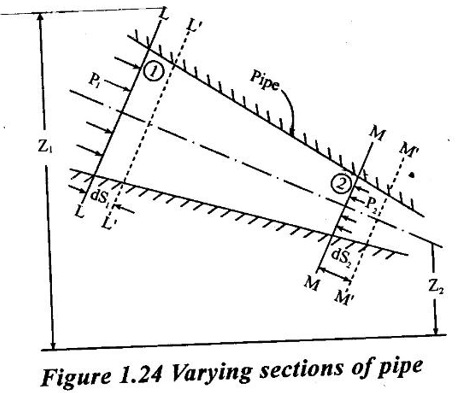
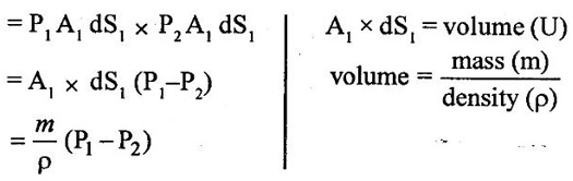
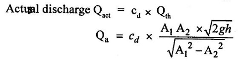
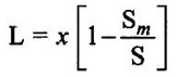
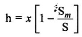
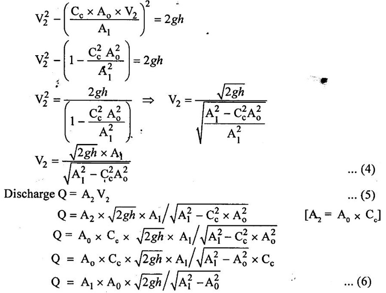
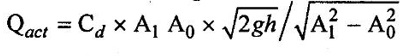
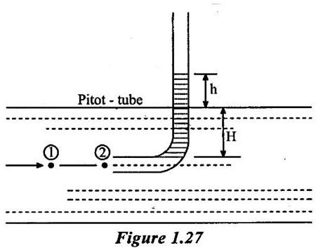
BERNOULLI'S EQUATION FOR IDEAL FLUID It may be stated as hollow in an ideal incompressible fluid. When the flow is steady and continuous, the sum of pressure energy, kinetic energy and potential energy is constant along a substance. Proof ✓ The flow is steady and continuous ✓ The liquid is ideal and incompressible if the velocity is uniform ✓ The velocity is uniform in entire cross sectional area and is equal to mean velocity. ✓ The pressure and gravity forces are only considered, others are neglected ✓ All frictional losses are neglected ✓ The flow is ir-rotational ✓ The ideal, incompressible liquid through a non-uniform pipe ✓ Consider the two sections of pipe L-L and M-M as shown in figure 1.24 and assume that the pipe is running full. There is continuity of flow between the two sections. Here i. The kinetic energy is increased ii. The potential energy is decreased iii. Work done is due to pressure Let, P1 – pressure at L to L section V1 - velocity at L to L section Z1 - height of the axis line from the datum line at L to L section A1 - area of the pipe at L to L section P2, V2, Z2 and A2 – corresponding values at section M to M Let the liquid between the two sections L-L and M-M move to L'L' and M'M' through very small length ds1 and ds2 This movement of both sections of liquid are equivalent to containing liquid of L'L' to MM. Because The sections of L'L' to MM containing liquid is unaffected Mass of fluid entering at LL (m) = density × volume = ρ1 × A1 × dS1 Mass of fluid leaving at MM (m) = density × volume = ρ2 × A2 × dS2 The mass of fluid in both sections are equal as per law of conservation of mass. [For same fluid ρ1 = ρ2] ρ1 × A1 × dS1 = ρ2 × A2 × dS2 Gain of kinetic energy = • m/2 (V22 – V12) loss of potential energy = mg (Z1 - Z2) workdone by pressure at section L-L to L'-L' = pressure force × distance = ρ1 × A1 × dS1 Workdone by pressure at section M-M to M'-M' = ρ2 × A2 × dS2 (-ve sign indicates that direction is P2 is opposite to that of P1) Networkdone by the pressure force = pressure force at section LL to L'L' - pressure force at section MM to M'M' = ρ1 × A1 × dS1 - ρ2 × A2 × dS2 According to continuity equation = A1 × dS1 = A2 × dS2 Principle of conservation of energy, Loss of potential energy + workdone by the pressure force = Gain of kinetic energy mg (Z1 - Z2) + m/ρ (P1 - P2) = m/2 (V22 – V12) divide the above equation by mg on both sides (Z1 - Z2) + (P1 - P2)/ ρ g = (V22 – V12)/2g (Z1 - Z2) + (P1 - P2)/ w = (V22 – V12)/2g (specific weight of liquid w = ρ g) Z1 + P1/w + V12/2g = Z2 + P2/w + V22/2g P/w + V2/2 + Z = constant 1. Velocity of flow across the cross sectional area of the pipe is assumed to be constant but it is not possible in actual practice. 2. The equation has been derived under the assumptions that no external force except gravity and pressure forces are acting on the liquid but in actual practice the force such as pipe friction is acting on the liquid 3. No loss of energy is assumed but during turbulent flow kinetic energy is converted in to heat energy 1. Bernoulli's equation for real fluid: Real fluid has viscosity, so there are some losses occur due to frictional force. These losses should be taken in to account while writing the Bernoulli's equation for real fluid. Z1 + P1/w + V12/2g = Z2 + P2/w + V22/2g + hL Where hL = loss of energy due to friction at inlet and outlet or between two sections considered 2. Bernoulli's equation or energy equation applications 1. Venturimeter 2. Orifice meter 3. Pitot tube 4. Flow nozzle 3. Venturimeter Venturimeter is a device which is used for measuring the rate of change of liquid through a pipe. The basic principle of venturimeter is that by reducing the cross sectional area along the pipe, pressure difference is created and this pressure difference is used for measure the rate of change of flow. Venturimeter works on the basis of principle of Bernoulli's equation. From the figure 1.25 A1, P1 and V1 - area, pressure and velocity at section 1 A2, P2 and V2 – area, pressure and velocity at section 2 Applying Bernoulli's equation for ideal fluid Z1 + P1/w + V12/2g = Z2 + P2/w + V22/2g Both sections height from the datum line or reference line is same hence Z1 = Z2 P1/w + V12/2g = P2/w + V22/2g P1/w - P2/w = V22/2g - V12/2g (P1 - P2)/w = (V22 - V12) /2g ... (1) The pressure head P = specific weight of liquid(w) × height of liquid in u-tube manometer (h) Height of liquid = P/w Apply the h value in equation (1) h = V22/2g - V12/2g ... (2) Continuity equation for ideal fluid: A1V1 = A2V2 V1 = A2V2 / A1 ... (3) Apply equation (3) in equation (2) The above discharge is theoretical. Therefore actual discharge is determined by introducing a constant coefficient of discharge cd. The average value of cd is about 0.98 Coefficient of discharge cd = actual discharge (Qact)/theorecticaldischarge(Qthe) Where A1 -area of the pipe in m2 A2 - area of the throat in m2 Cd - coefficient of discharge no unit h - Height difference of liquid in the u-tube manometer in m 1. Loss of head is small and hence high c, value is obtained. 2. No wear and tear. 3. Loss like hood of becoming clogged with sediments. 4. Suitable for large flow of water, process fluids, wastes, gases and suspended solids. Disadvantages of venturimeter 1. Long laying length. 2. More space requirement. 3. Possibility of cavitations. 4. More expensive in installation and replacement. 1. Using U-tube manometer in horizontal venturimeter Case (1) Specific gravity of measuring liquid in manometer (Sm) is less than specific gravity of flowing liquid (s) S > Sm x - Manometer height difference Sm - Specific gravity of mercury S - Specific gravity of water Case (2) Sm > S 2. Using u-tube manometer in inclined venturimeter Case (1) S > Sm Case (2) Sm > S Using pressure gauge in venturimeter 1. h = P1/w − P2/w Z1 = Z2 in horizontal venturimeter 2. h = P1/w + Z1 – P2/w + Z2 inclined venturimeter An orifice meter is a simple device used for measuring discharge of fluid through a pipe. It works on the basis of Bernoulli's equations like venturimeter i.e by reducing the cross sectional area of the pipe. A pressure difference is developed between two sections. From the pressure difference, the discharge can be calculated. In its simplest form it consists of a thin plate having a sharp edged hole at its center. The orifice plate is clamped between the two flanges of a pipe line. The orifice diameter varies from 0.4 to 0.8 times the pipe diameter(mostly 0.5 times). A differential manometer or two pressure gauges are placed one at section 1 on the upstream side of the orifice plate and the other at section 2 on the down stream side of the orificeplate. Section 1 is placed at a distance of 1.5 to 2 times of the pipe diameter and section 2 is placed at a distance about half the diameter of orifice from the orifice plate on the downstream side as shown in figure 1.26. P1, V1 and A1 are pressure, velocity and area at the section 1 respectively: P2, V2 and A2 are corresponding at the section 2 respectively as shown in figure 1.26. When fluid is flowing through orifice the diameter of the liquid jet will be reduced (contracted) in front of the orifice. This one, refers to vena contracta. when a fluid flows through the orifice, it contracts and its diameter reduced at a distance d/2 from the orifice. The point where the flow is contracted is called vena contracta. Beyond this vena contracta the fluid jet diverse. The ratio of the area of vena contracta to the area of the orifice is known as coefficient of contraction (Cc). Cc varies from 0.61 to 0.69 generally taken as 0.64. Coefficient of contraction Cc = area of the jet at venacontracta/ area of the orifice Cc = A2/A0 Where A0 = area of the orifice Applying Bernoulli's equation, P1/w + V12/2g + Z1 = P2/w + V22/2g + Z2 (Z1 = Z2) P1/w + V12/2g = P2/w + V22/2g P1/w = V22/2g – V12/2g h = V22/2g – V12/2g h = V22 – V12/2g V22 – V12 = 2gh …..(1) Applying continuity equation A1V1 = A2V2 V1 = A2V2/A1 …..(2) Co-efficient of Cc = A2/A0 A2 = Cc × A0 …..(3) Equation (3) applying in equation (2) V1 = Cc × A0 × V2/A1 Substitute v1 value in equation (1) The above discharge is theoretical. Thus the actual discharge is determined by introducing co-efficient of discharge (Cd). Co-efficient of discharge Cd = actual discharge/theoretical discharge ✓ Low initial cost ✓ Installation and replacement is easy ✓ Less space as compared ✓ It can be used in wide base of pipe ✓ Less accuracy compared to venturimeter ✓ Its operation is affected due to vibration ✓ High loss of head Pitot tube is a device used for measuring the velocity of flow at any point in pipe or a channel. It is based on the principle that if the velocity of flow at a point becomes zero, then the pressure is increased due to the conversion of the kinetic energy in to pressure energy. In the simplest form, the pitot tube consist of a glass tube, bent at right angles as shown in figure 1.27. Consider two points (1) and (2) at same level in such a way that point (2) is just at the inlet of pitot tube and point (1) is far away from the tube. Let P1 = intensity of pressure at point (1) V1 = velocity of flow at (1) P2 = intensity of pressure at point (2) V2 = velocity of flow at (2), which is zero H = depth of tube in the liquid h = rise of liquid in the tube above the free surface Applying bernoullis equation at points (1) and (2) we get But Z1 = Z2 as points (1) and (2) are on same line Also V2 = 0 Substituting these values in equation (1) we get, This is theoretical velocity. Actual velocity is given by The various arrangement of pitot-tube adopted are as shown in figure 1.28. (i) Pitot tube along with a vertical piezometer (ii) Pitot tube connected with piezometer (iii) Pitot tube and vertical piezometer tube with differential V-tube manometer (iv) Pitot static tube which consists of two circular concentric tubes one inside the other. The outlet is connected to the differential manometer where the difference of pressure head his measured by knowing the differences of the level of manometer liquid say x Formula used for problems based on continuity equation (1) Rate of flow = A × V Area of pipe (A) in m2 Velocity of flow (V) in m/s (2) Continuity equation for ideal fluid A1V1 = A2V2 (3) Continuity equation for real fluid ρ1A1V1 = ρ2A2V2Assumptions:
Limitations:


Advantages of venturimeter


4. Orifice meter
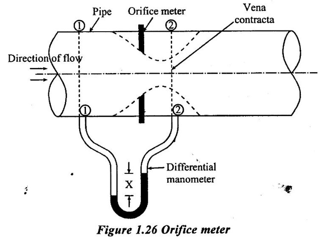
Vena contracta
Advantages
Disadvantages

5. Pitot Tube


Fluid Mechanics and Machinery: Unit 1: Fluid Properties and Flow Characteristics : Tag: : Statement, Proof, Formula, Advantages, Disadvantages, Limitations - Bernoulli's Equation for Ideal Fluid
Related Topics
Related Subjects
Fluid Mechanics and Machinery
CE3391 3rd semester Mechanical Dept | 2021 Regulation | 3rd Semester Mechanical Dept 2021 Regulation