Basic Electrical and Electronics Engineering: Unit I: Electrical Circuits
AC Through Series RLC Circuit
Consider a circuit consists of pure resistance R, pure inductance L and capacitance C are connected in series as shown in figure 1.67.
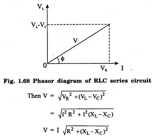
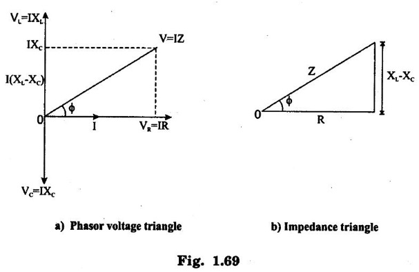
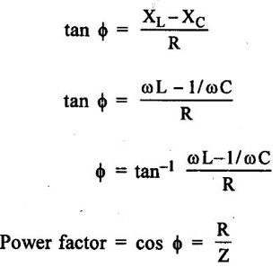
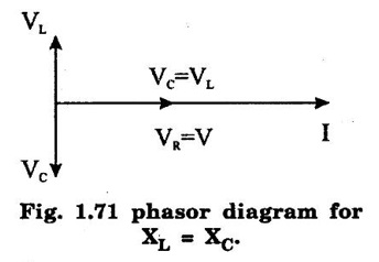
AC THROUGH SERIES RLC CIRCUIT Consider a circuit consists of pure resistance R, pure inductance L and capacitance C are connected in series as shown in figure 1.67. The ac voltage is given by V = Vm sin ωt VR = Voltage across resistance R = IR ∠ 0° VL = Voltage (rms value) across inductor L = I XL ∠ 490° = j I XL VC = Voltage (rms value) capacitor I XC ∠-90° = -j I XC Apply Kirchoff's laws, in the circuit V = VR + VL + VC The phasor diagram depends upon the magnitudes of VL and VC which depends on XL and XC values. In the series circuit, I is taken as reference. Voltage across R = VR = IR where VR is in phase with I and is equal to VR ∠ 0° Voltage across L = VL = j I XL where VL leads I by 90° and is equal to VL ∠ 90° Voltage across C = VC = j IXC where VC lags I by 90° and is equal to VC ∠ 90° ⸫ Applied voltage V = VR + VL + VC ….. (1) = IR + j IXC − jIXC = I (R + jXL − jXC) = I (R + j (XL − XC)] …. (2) = IZ where Z = R + j (XL - XC) …. (3) = |Z| ∠ϕ Here Z is the complex impedance of the circuit. If XL > XC, circuit behave as RL circuit. If XL < XC, circuit behave as RC circuit. The source voltage V can be obtained from the phasor diagram as complex sum of VR, VL, VC. Rearranging the above equation There are three cases to the general RLC series circuit as follows: Case (i): When XL > XC, the total reactance of the circuit is inductive, the circuit act as RL circuit. From the phasor voltage triangle 1.69 (a) we can draw impedance angle as in figure 1.69 (b). From the figure 1.69 (a), tan ϕ is positive, and current lags the supply voltage by an angle ϕ. Therefore powerfactor is lagging. Case (ii) When XC > XL, the total reactance of the circuit capacitive, the circuit act as RC circuit. From the phasor voltage triangle, we can draw the impedance angle. From the figure 1.70(a) tan ϕ is negative and the current leads the supply voltage by an angle ϕ. Therefore power factor is lead. Case 3: When XL = XC the total reactance is zero. The current and supply voltage are inphase. From phase diagram V = IR V = IR V = IZ where Z = R Real power P = VI cos ϕ watts Reactive power Q = VI sin ϕ VAR Apparent power S = VI volt amp


Basic Electrical and Electronics Engineering: Unit I: Electrical Circuits : Tag: : - AC Through Series RLC Circuit
Related Topics
Related Subjects

Basic Electrical and Electronics Engineering
BE3251 2nd semester Mechanical Dept | 2021 Regulation | 2nd Semester Mechanical Dept 2021 Regulation

Basic Electrical and Electronics Engineering
BE3251 2nd Semester CSE Dept 2021 | Regulation | 2nd Semester CSE Dept 2021 Regulation