Basic Electrical and Electronics Engineering: Unit I: Electrical Circuits
AC Through Pure Resistance alone
Electrical Circuits
The circuit containing a pure resistance R is shown in fig. 1.59 (a). Let the applied voltage be given by the equation,
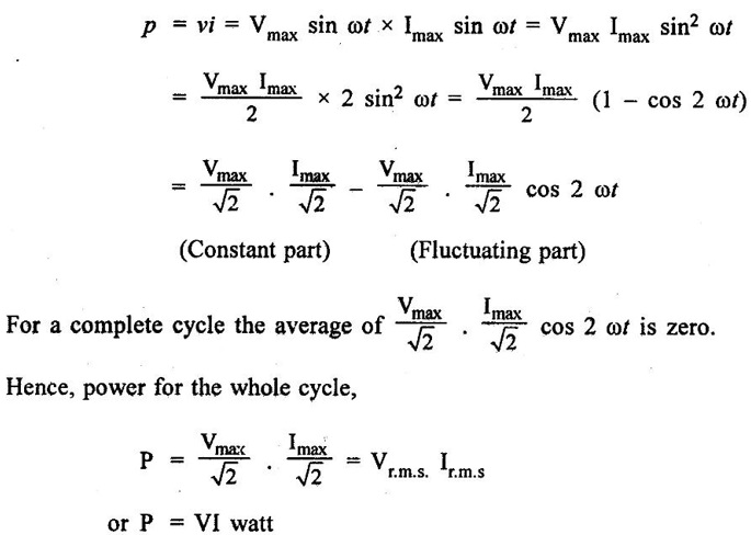
AC THROUGH PURE RESISTANCE ALONE The circuit containing a pure resistance R is shown in fig. 1.59 (a). Let the applied voltage be given by the equation, The value of current will be maximum if sin ωt = 1 or (ωt = 90°) Substituting this value in equation (2), we get i = Imax sin ωt ... (3) Comparing (1) and (3), we find that alternating voltage and current are in phase with each other as shown in fig. 1.59 (b), also shown vectorially in fig. 1.55 (c). The instantaneous power, where V = R.M.S. value of applied voltage, and I = R.M.S. value of the current. It may be noted from the Fig. 1.59 (c) the power cycle in a purely resistive circuit never becomes zero (or) negative. Hence in pure resistive circuit we have: 1. Current is in phase with the voltage. 2. Current I = V/R where I and V are r.m.s. values of current and voltage. 3. Power in the circuit, P = VI = I2R. The instantaneous value of current flowing through the resistance R will be,

Power
Basic Electrical and Electronics Engineering: Unit I: Electrical Circuits : Tag: : Electrical Circuits - AC Through Pure Resistance alone
Related Topics
Related Subjects

Basic Electrical and Electronics Engineering
BE3251 2nd semester Mechanical Dept | 2021 Regulation | 2nd Semester Mechanical Dept 2021 Regulation

Basic Electrical and Electronics Engineering
BE3251 2nd Semester CSE Dept 2021 | Regulation | 2nd Semester CSE Dept 2021 Regulation