Basic Electrical and Electronics Engineering: Unit I: Electrical Circuits
AC Through Pure Capacitance alone
Electrical Circuits
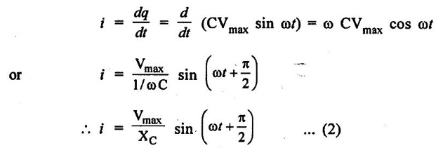
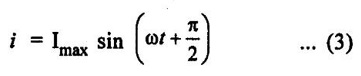
Figure 1.62(a) shows the circuit containing a pure capacitor of capacitance C farad. Consider the alternating voltage applied across the circuit be given by the equation,
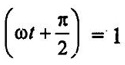
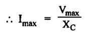
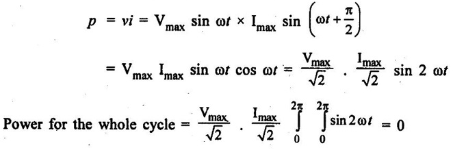
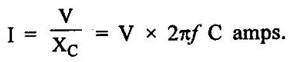
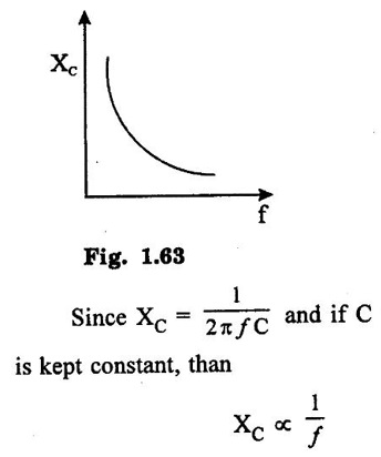
AC THROUGH PURE CAPACITANCE ALONE Figure 1.62(a) shows the circuit containing a pure capacitor of capacitance C farad. Consider the alternating voltage applied across the circuit be given by the equation, Charge on the capacitor at any instant, q = Cv Current through the circuit, The denominator XC = 1/ωC (opposition offered to the flow of alternating current by a pure capacitor) is known as capacitive reactance. It is given in ohms if C is in farad and ∞ in radian/second. The value of current will be maximum when sin Substituting this value in equation (ii), we get Instantaneous power, This fact is graphically illustrated in fig. 1.62 (c). It may be noted that, during the first quarter cycle, what so ever power or energy is supplied by the source is stored in the electric field set-up between the capacitor plates. During the next quarter cycle the electric field collapses and the power or energy stored in the field is returned to the source. The proces is repeated in each alternation and this circuit does not absorb any power. Hence in a pure capacitive circuit, we have 1. 2. Current always leads the applied voltage by 90°. 3. Power consumed is zero. Fig. 1.63 shows the variation. As the frequency increases XC decreases, so the current increases.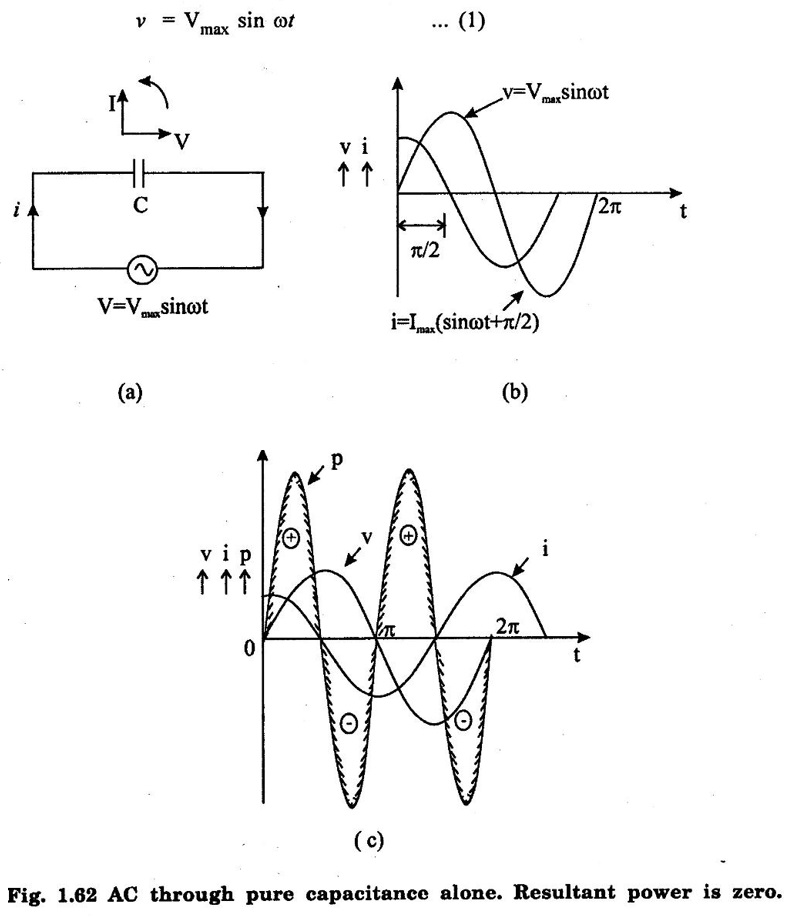
Power
Variation of XC and ƒ :
Basic Electrical and Electronics Engineering: Unit I: Electrical Circuits : Tag: : Electrical Circuits - AC Through Pure Capacitance alone
Related Topics
Related Subjects

Basic Electrical and Electronics Engineering
BE3251 2nd semester Mechanical Dept | 2021 Regulation | 2nd Semester Mechanical Dept 2021 Regulation

Basic Electrical and Electronics Engineering
BE3251 2nd Semester CSE Dept 2021 | Regulation | 2nd Semester CSE Dept 2021 Regulation