Basic Electrical and Electronics Engineering: Unit I: Electrical Circuits
A.C. Through Pure Inductance alone
Electrical Circuits
Whenever an alternating voltage is applied to a purely inductive coil, a back e.m.f. is induced due to the self-inductance of the coil.
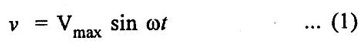
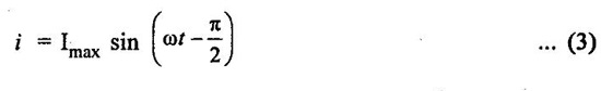
A.C. THROUGH PURE INDUCTANCE ALONE Fig. 1.60(a) shows the circuit containing a pure inductance of L henry. Consider the alternating voltage applied across the circuit be given by the equation, Whenever an alternating voltage is applied to a purely inductive coil, a back e.m.f. is induced due to the self-inductance of the coil. This back e.m.f. opposes the rise or fall of the current through the coil. Since there is no ohmic drop in this case, hence the applied voltage has to overcome this induced e.m.f. only. The value of current will be maximum when sin Substituting this value in equation (2), we get Hence average power consumed in a pure inductive circuit is zero. Hence in a pure inductive circuit, we have : 1. Current 2. Current always lags behind the voltage by 90°. 3. Average power consumed is zero. Since XL = ωL = 2πfL, and here if L is constant, then XL ∝ f Fig. 1.61, shows the variation. As frequency is increased XL increases and the current taken by the circuit decreases.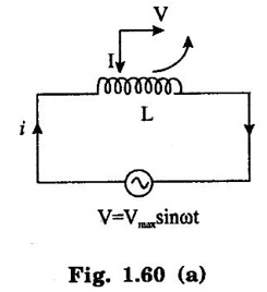
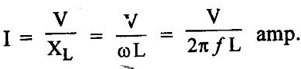
 where XL = ωL (opposition offered to the flow of alternating current by a pure XL inductances) and is called Inductive reactance. It is given in ohms if L is in henry and o is in radian / second.

Power


Variation of XL and ƒ:
Basic Electrical and Electronics Engineering: Unit I: Electrical Circuits : Tag: : Electrical Circuits - A.C. Through Pure Inductance alone
Related Topics
Related Subjects

Basic Electrical and Electronics Engineering
BE3251 2nd semester Mechanical Dept | 2021 Regulation | 2nd Semester Mechanical Dept 2021 Regulation

Basic Electrical and Electronics Engineering
BE3251 2nd Semester CSE Dept 2021 | Regulation | 2nd Semester CSE Dept 2021 Regulation