Manufacturing Technology: Unit II: Turning Machines
work holding devices
Turning Machines - Manufacturing Technology
Some of the standard work holding devices used to hold the work in a lathe are given below.
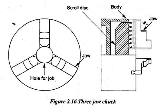
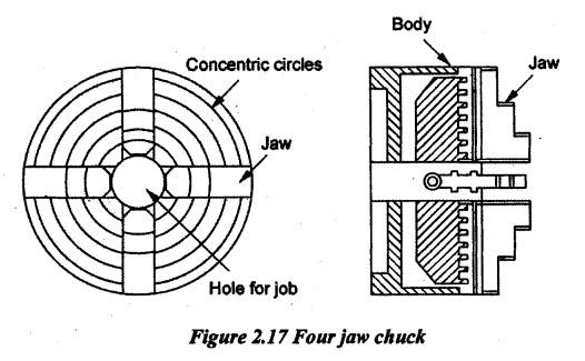
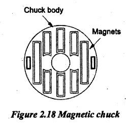
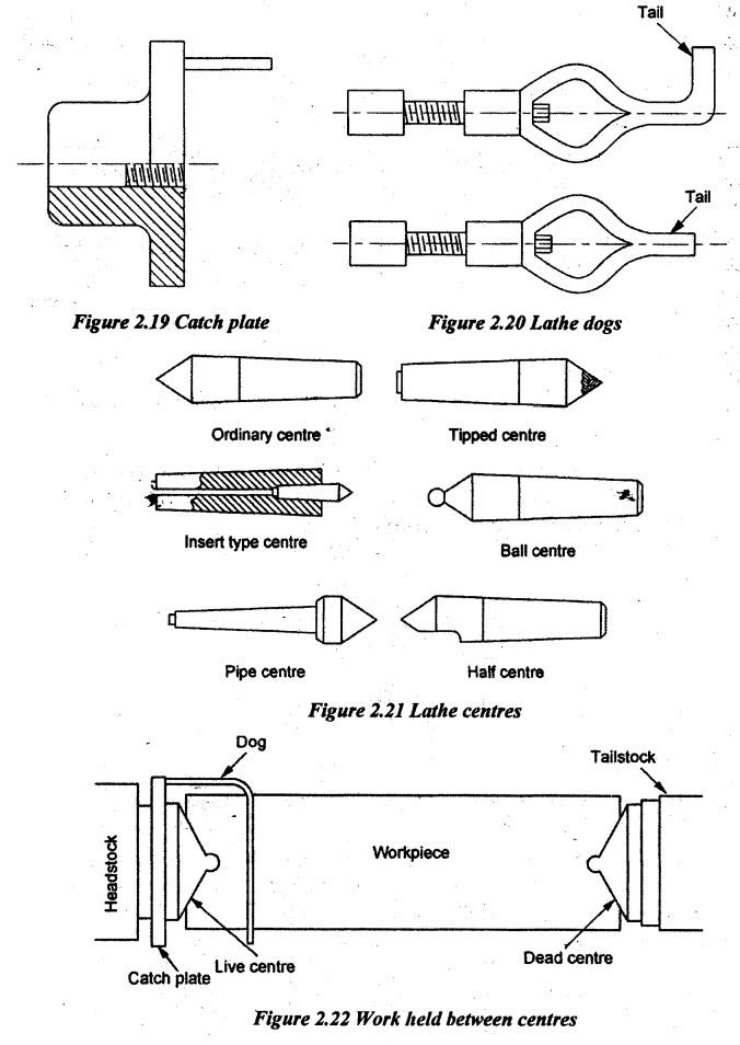
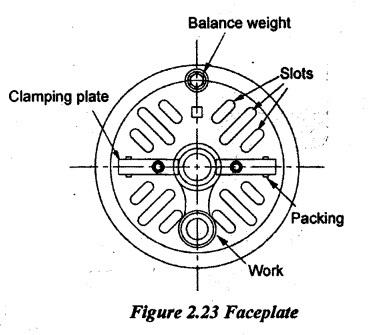
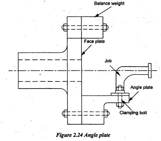
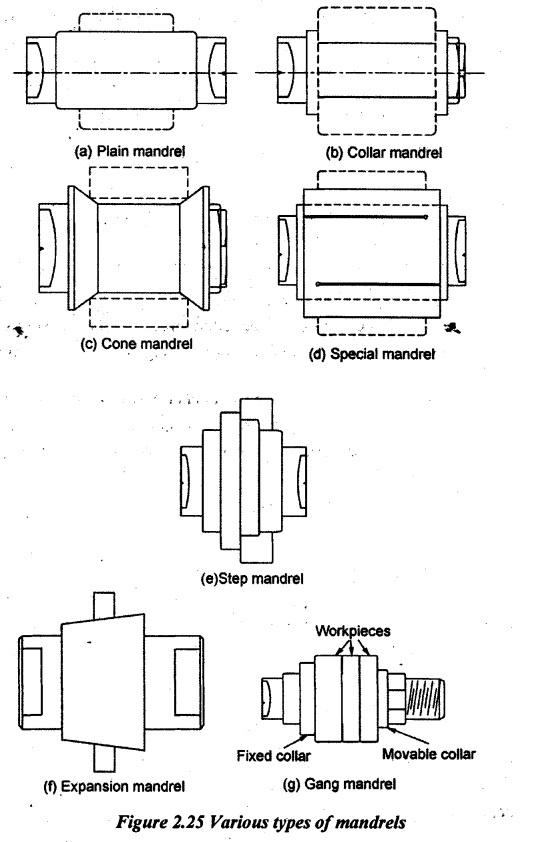
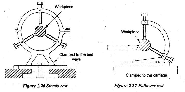
WORK HOLDING DEVICES Some of the standard work holding devices used to hold the work in a lathe are given below. (i) Chucks (ii) Centres (iii) Faceplate (iv) Angle plate (v) Mandrels (vi) Steady and follower rest. Chucks are used to hold the workpieces of small length (L < 4D) and large diameters. It can also hold the irregular shape workpieces. Workpieces which cannot be mounted between centres are mounted in chucks. A chuck is attached to the headstock spindle of the lathe. The work is clamped between jaws of the chuck and jaws are tightened. The right end of the workpiece can be supported by the dead centre if needed. There are three types of chucks. (i) Three jaw chuck or self-centering chuck (ii) Four jaw chuck or Independent chuck (iii) Magnetic chuck. 1. Three jaw or self-centering chuck: As the name implies, it has three jaws. When the chuck key is turned, all jaws will move for equal distance in the radial direction. The chuck has an internal mechanism to simultaneously move three jaws. Hence, the work can automatically be centered and quickly. It consists of a circular disc. The disc has a spiral scroll of the front and bevel teeth at its back. Three bevel pinions are fitted with the bevel teeth of the disc. By rotating any one of these bevel pinions, the disc will rotate. Hence, jaws meshed with spiral scroll move. This chuck is used for holding round, hexagonal and other regular shaped workpiece. 2. Four jaw or Independent Chuck: It has four jaws. Each jaw can independently be moved. These jaws have slots at the backside to mesh with screws. These screws can be screwed in or out of the body. The screws have a square hole at the top to receive chuck key. When the chuck key is turned in the slot, the particular jaw will only be moved. Therefore, the irregular job can be held in this chuck. These jaws can be reversed for holding large hollow workpieces. Concentric circles are inscribed on the face of the chuck for quick centering of workpieces. 3. Magnetic chuck: Thin jobs can be held by means of a magnetic chuck. The chuck gets magnetic power from an electromagnet. Due to magnetic power, the job is held in position on the flat face. The main disadvantage is that the magnetic material can only be held on this chuck. Generally, the long shaft can be held between centres. Catch plate and dog carriers are used to hold the job between centres. The catch plate is in the form of a circular disc as shown in Figure 2.19 and it is screwed on the spindle nose. The various dog carriers are shown in Figure 2.20. These dog carriers are clamped to the job by a screw. The tail of the dog carrier is attached to the catch plate. The live centre is inserted in the headstock spindle. The tailstock carries a dead centre. Small holes are drilled on both ends of the job and they are supported by centres. The various lathe centres are shown in Figure 2.21. When the spindle rotates, the workpiece will rotate through the catch plate and carrier arrangement as shown in Figure 2.22. The live centre will revolve the workpiece and the dead centre will support the right end of the work. The faceplate is a circular cast iron disc and has four T-slots and a number of plain radial slots as shown in Figure 2.23. These slots are used for holding the work by bolts and clamps. It is highly efficient for holding the asymmetrical work or work of complex and irregular shapes which are inconvenient to clamp by other means. When the spindle rotates, the faceplate will also rotate. So, the work will rotate. Angle plate is a cast iron block and it has two accurately machined faces at right angle to each other. It has holes and slots on both faces so that its one face may be clamped on the faceplate and the workpiece is mounted on the other face. When the spindle rotates, the faceplate will also rotate. So, the angle plate and job also rotate. Usually, the counterweights are fitted to balance the weight of the job. The job is eccentrically fitted or fitted in angle plate. The angle plate used for holding elbow piece is shown in Figure 2.24. Mandrels are used for holding hollow workpieces. The work revolves with the mandrel which is mounted between two centres. There are different types of mandrels used for various types of jobs. They are shown in Figure 2.25. The outside diameter of mandrel should be equal to the inside diameter of the job. The rest is a device which supports long workpieces i.e. L/D > 10 or 12 when machined between centres or held by a chuck. It is placed in between headstock and tailstock. It prevents the vibration and bending of the workpiece. There are two types of rests. (a) Steady rest (b) Follower rest. 1. Steady rest: These types of rests are fixed on bed ways of the lathe by clamping bolts. There is a cast iron base which is used to clamp the rest on the bed. The upper portion of the rest is hinged at one end. It is used to remove the job without disturbing the steady rest. The workpiece is supported by three jaws arranged as shown in Figure 2.26. The jaws can separately be adjusted in the radial direction. For the wark to be turned at high velocity, the jaws have built up balls or roller bearings to support it. After setting the jaws over the workpiece, the rest is clamped to the lathe bed to the required position. Since the carriage cannot pass over it the job is turned in two stages by reversing one end after half machining the length. For longer workpieces, two or more steady rests can be used. 2. Follower rest: The rest is mounted on the saddle and it moves together with the tool. It has a C type casting and two adjustable jaws to support the workpiece shown in Figure 2.27. The jaws always follow the tool. Therefore, it gives a continuous support to the workpiece.1. Chucks
2. Centres
3. Faceplate
4. Angle Plate
5. Mandrels
6. Steady and Follower Rest
Manufacturing Technology: Unit II: Turning Machines : Tag: : Turning Machines - Manufacturing Technology - work holding devices
Related Topics
Related Subjects

Manufacturing Technology
ME3493 4th semester Mechanical Dept | 2021 Regulation | 4th Semester Mechanical Dept 2021 Regulation