Theory of Machines: Unit II: Gears and Gear Trains
Velocity ratio for epicyclic gear train
Gears and Gear Trains - Theory of Machines
Velocity ratio for epicyclic gear trains is usually found by the following two methods:
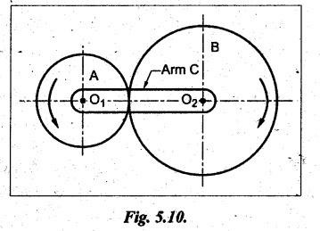
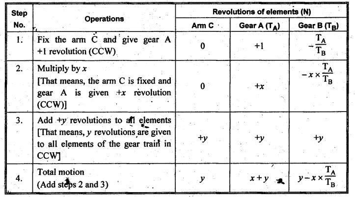
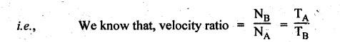
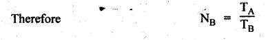
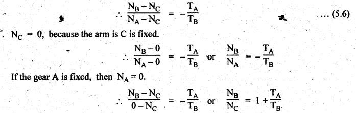
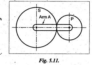
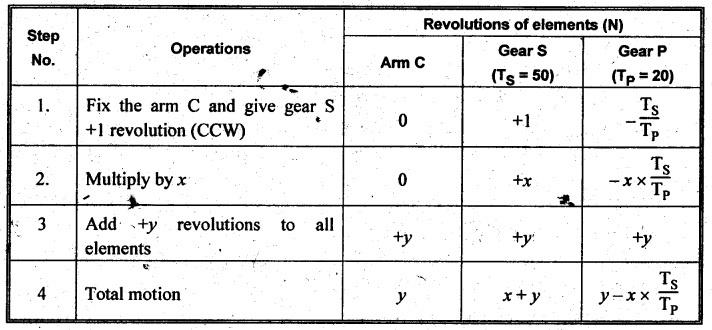
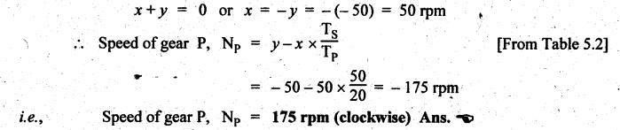
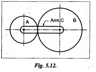
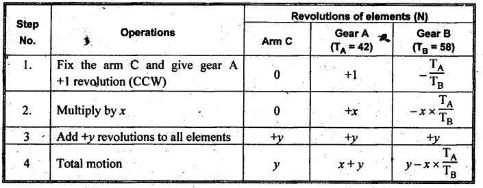
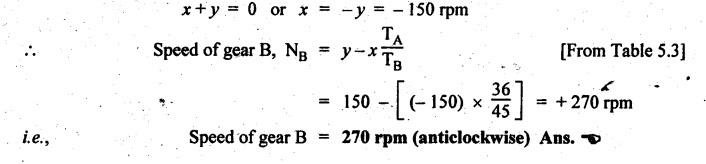
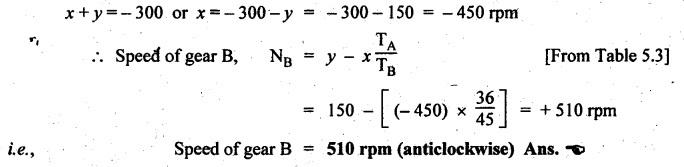
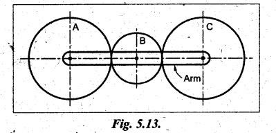
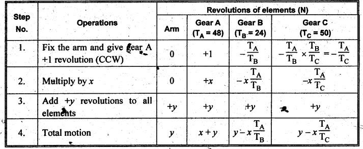
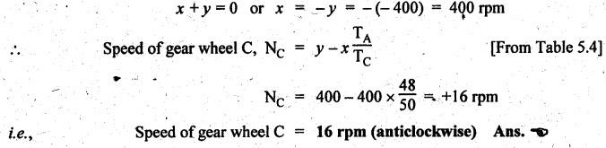
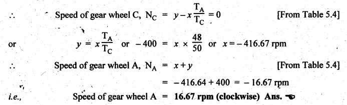
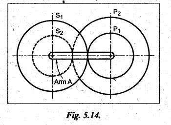
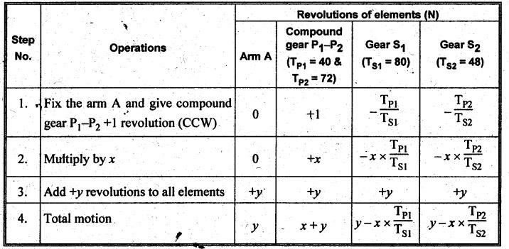
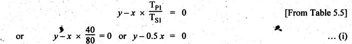
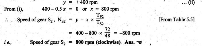
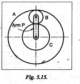
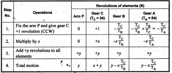
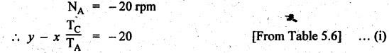
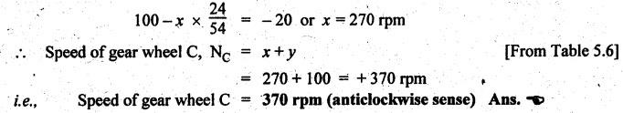
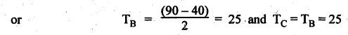
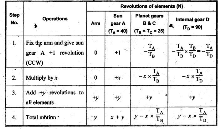
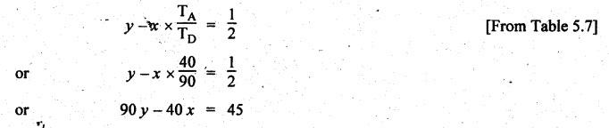
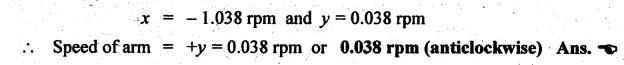
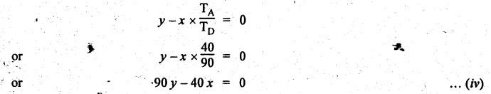
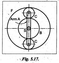
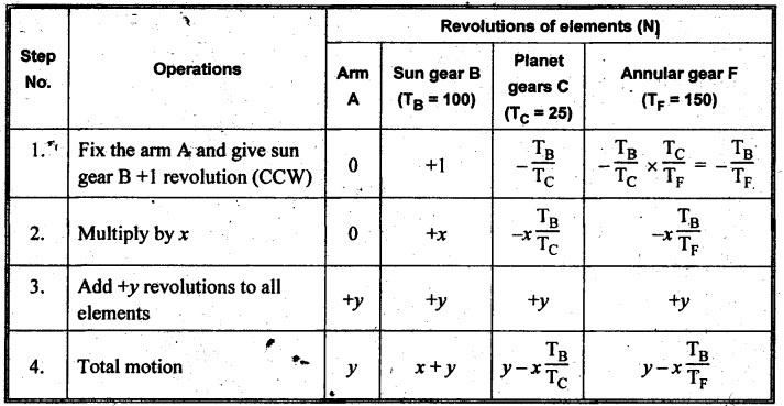
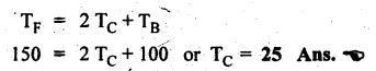
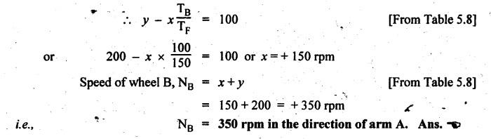
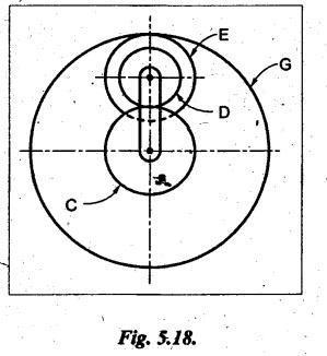
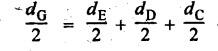
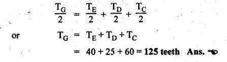
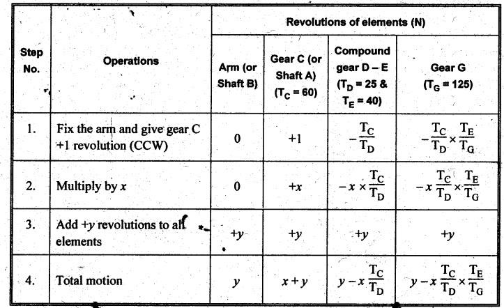
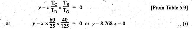
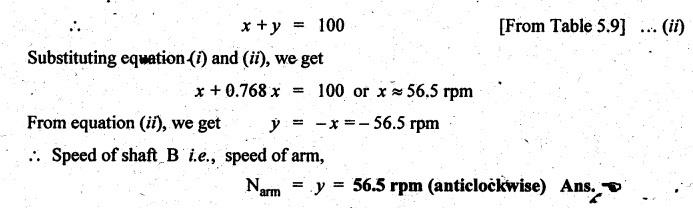
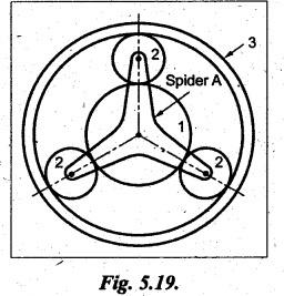
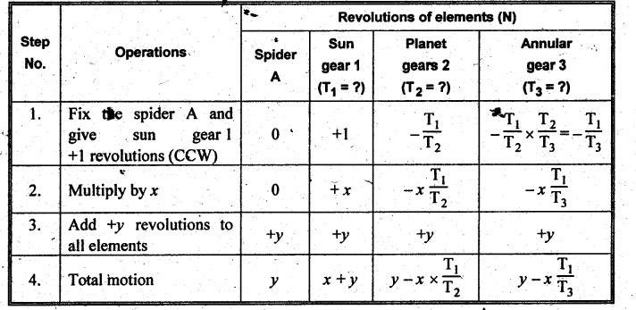
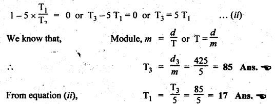
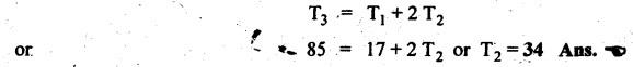
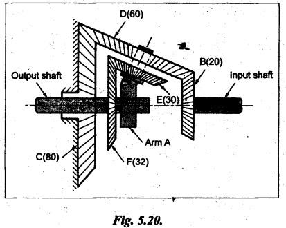
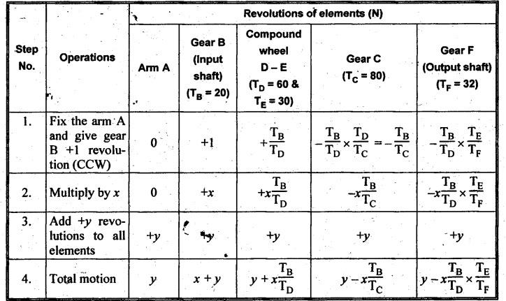
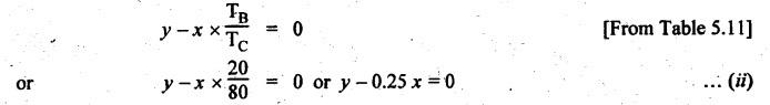
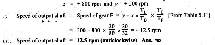
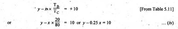
VELOCITY RATIO OF EPICYCLIC GEAR TRAIN Velocity ratio for epicyclic gear trains is usually found by the following two methods: 1. Tabulation method, and 2. Algebraic (or formula or relative velocity) method. Consider an epicyclic gear trains as shown in Fig.5.10. Let TA = Number of teeth on gear A, and TB = Number of teeth on gear B. The motion or rotations of the various elements are shown in the Table 5.1. Table 5.1. Motion of elements Procedure: Step 1: Lock (i.e., fix) the arm and assume the other gear wheels are free to rotate. By fixing the arm, the epicyclic gear train becomes a simple reverted gear train, which is simpler to analyse. When gear A is given one revolution anticlockwise and as a consequence gear B will rotate by TA / TB revolutions clockwise. Since gear A rotates one revolution anticlockwise i.e., NA = +1. But the gear B rotates in the opposite direction, i.e., in the clockwise direction, so This statement of relative motion is entered in the first row of the table (see Table 5.1). Step 2: Multiply each row by '+x', and write the same in the second row. This means that with the arm fixed, the gear A is given +x revolutions. Step 3: Add '+y' revolutions to all the quantities in the second row and make the recordings in the third row (see Table 5.1). Step 4: Finally, the motion of each element of the gear train is added up and entered in the fourth row (see Table 5.1). Result: By applying the given conditions, the values of x and y are found from the tables. Having known x and y values, the revolutions made by any of the gear wheels can be obtained. The +ve sign is used when the gear rotates in anticlockwise direction and the -ve sign is for clockwise rotation of the gear. In this method, the motion of each element of the epicyclic gear train is given in the form of equations. Referring to Fig.5.5, we can write Speed of the gear A relative to the arm C = NA - NC and Speed of the gear B relative to the arm C = NB - NC The speeds of gears A and B are determined relative to the arm C, it means that the arm C is fixed. In such a case, the velocity ratio of gears A and B depend only on their teeth ratio. Note The above two methods can be adopted to all the problems on epicyclic gear train. The tabulation method is easier and also gives analysis of all the elements. Hence this method is mostly used in solving problems on epicyclic gear trains. Example 5.5 In an epicyclic gear train, the members are fixed sun gear, S, with 50 teeth, planet gear, P, with 20 teeth and the arm, A, which carries the planet. The arm rotates about the sun gear axis at 50 rpm in clockwise rotation. Sketch the arrangement and determine the speed of the planet gear and its direction of rotation. Give Data: NS = 0; TS = 50; TP = 20; NA = 50 rpm (clockwise). Solution: The arrangement of given epicyclic gear train is shown in Fig.5.11. The motion of various elements are shown in Table 5.2. Table 5.2. Motion of elements Given conditions are: (i) Arm C rotates at 50 rpm clockwise, so y = - 50 rpm (ii) Gear S is fixed, so Example 5.6 In an epicyclic gear train, an arm carries two gears A and B`having 36 and 45 teeth respectively. If the arm rotates at 150 rpm in the anticlockwise direction about the centre of the gear A which is fixed, determine the speed of gear B. If the gear A instead of being fixed, makes 300 rpm in the clockwise direction, what will be the speed of gear B? [A.U., Nov/Dec 2010; Apr/May 2011] Given data: TA = 36; TB = 45; NC = 150 rpm (anticlockwise) Solution: For better understanding, we shall solve this example, first by tabulation method and then by algebraic method. The arrangement of given epicyclic gear train is shown in Fig.5.12. The motion of various elements are shown in Table 5.3. Table 5.3. Motion of elements Speed of gear B when gear A is fixed: Given conditions are: (i) Arm rotates at 150 rpm CCW, so y = + 150 rpm (ii) Gear A is fixed, so Speed of gear B when gear A makes 300 rpm clockwise: Given conditions are: (i) Arm rotates at 150 rpm CCW, so y = + 150 rpm (ii) Gear A rotates 300 rpm CW, so We know that when the gears A and B revolve in opposite directions (refer Section 5.9.2), Speed of gear B when gear A is fixed: When gear A is fixed, the arm rotates at 150 rpm anticlockwise, so NA = 0 and NC = +150 rpm Substituting in equation (i), we get Speed of gear B when gear A makes 300 rpm clockwise: Since the gear makes 300 rpm clockwise, so NA = - 300 rpm Example 5.7 In an epicyclic gear train as shown in Fig.5.13, the number of teeth on gear wheel A, B and C are 48, 24 and 50 respectively. If the arm rotates at 400 rpm clockwise, find (i) Speed of gear wheel C when A is fixed, and (ii) Speed of gear wheel A when C is fixed. Given data: TA = 48; TB = 24; TC = 50; NC = 400 rpm (clockwise) Solution: Refer Fig.5.13. The motion of various elements are shown in Table 5.4. Table 5.4. Motion of elements (i) Speed of gear wheel C when A is fixed: Given conditions are: (a) Arm rotates at 400 rpm clockwise, so y = -400 rpm (b) Gear A is fixed, so (ii) Speed of gear wheel A when C is fixed: Given conditions are: (a) Arm rotates at 400 rpm clockwise, so y = -400 rpm (b) Gear wheel C is fixed, so NC = 0 Example 5.8 In a reverted epicyclic gear train, the arm A carries two gears S, and S2 and a compound gear PP2. The gear S, meshes with gear P, and the gear S2 meshes with gear P2. The numbers of teeth on gears S1, S2 and P2 are 80, 48 and 72 respectively. Find the speed and direction of gear S2 when gear S, is fixed and arm A makes 400 rpm counter clockwise. Given data: TS1 = 80; TS2 = 48; TP2 = 72; NS1 = 0; NA = 400 rpm (CCW) Solution: The arrangement of given reverted epicyclic gear train is shown in Fig.5.14. From the geometry of Fig.5.14, we can write dS1 + dP1 = dS2 + dP2 where dS1, dS2, dP1 and dP2 are pitch circle diameters of gears S1, S2, P1 and P2 respectively. When the module is same, the number of teeth on each gear are proportional to their pitch circle diameters. ⸫ TS1 + TP1 = TS2 + TP2 or TP1 = TS2 + TP2 - TS1 = 48 + 72 - 80 = 40 The motion of various elements is shown in Table 5.5. Table 5.5. Motion of elements Given conditions are: (i) Gear S1 is fixed, so (ii) Arm A makes 400 rpm counter clockwise, so Example 5.9 In an epicyclic gear train an annular wheel A having 54 teeth meshes with a planet wheel B which gears with a sun wheel C, the wheels A and C being coaxial. The wheel B is carried on a pin fixed on one end of arm P which rotates about the axis of the wheels A and C. If the wheel A makes 20 rpm in a clockwise sense and the arm rotates at 100 rpm in the anticlockwise direction and the wheel C has 24 teeth, determine the speed and sense of rotation of wheel C. Given data: TA = 54; NA = 20 rpm (clockwise); Narm = 100 rpm (CCW); TC = 24 Solution: The arrangement of given epicyclic gear train is shown in Fig.5.15. The motion of various elements is shown in Table 5.6. Table 5.6. Motion of elements Given conditions are: (i) Wheel A makes 20 rpm in clockwise, so (ii) Arm P makes 100 rpm in anticlockwise, so From conditions (i) and (ii), we get Example 5.10 An epicyclic gear train is arranged as shown in Fig.5.16. The internal gear D has 90 teeth and the sun gear A has 40 teeth. The two planet gears B and C are identical and they are attached to an arm as shown. How many revolutions does the arm make: (i) when 'A' makes one revolution clockwise and 'D' makes half a revolution anticlockwise, and (ii) when 'A' makes one revolution clockwise and ‘D' remains stationary. Given data: TA = 40; TD = 90 Solution: Refer Fig.5.16. From the geometry of Fig.5.16, we can write where dA, dB, dC and dD are the pitch circle diameters of the gears A, B, C and D respectively. We know that for the same module, the number of teeth are proportional to the pitch circle diameters. Therefore TD = TA + 2 TB or 90 = 40 + 2 TB The motion of various elements is shown in Table 5.7. Table 5.7. Motion of elements (i) Speed of arm when A makes 1 revolution in clockwise and D makes half revolution in anticlockwise: Given conditions are: (i) Gear A makes 1 revolution clockwise, so (ii) Gear D makes half revolution anticlockwise, so On solving equations (i) and (ii), we get (ii) Speed of arm when A makes 1 revolution in clockwise and D is stationary: Given conditions are: (i) Gear A makes 1 revolution clockwise, so (ii) Gear D is stationary, so On solving equations (iii) and (iv), we get Example 5.11 In an epicyclic gear train as shown in Fig.5.17, the arm A is fixed to shaft S. The wheel B having 100 teeth rotates freely on the shaft S and wheel F with 150 teeth is separately driven. If the arm A runs at 200 rpm and wheel F at 100 rpm in the same direction, find: (i) Number of teeth on wheel C, and (ii) Speed of wheel B. Given data: TB = 100; TF = 150; NA = 200 rpm; NF = 100 rpm Solution: Refer Fig.5.17. The motion of various elements is shown in Table 5.8. Table 5.8. Motion of elements (i) Number of teeth on wheel C: From the geometry of Fig.5.17, we can write dF = dC + dC + dB = 2 dC + dB where dB, dC and dF are the pitch circle diameters of the wheels B, and F respectively. We know that for the same module, the number of teeth are proportional to their pitch circle diameters. Therefore (ii) Speed of wheel B: Given conditions are: (a) Speed of arm A = y + 200 rpm (assuming arm A and gear F rotates in CCW direction). (b) Speed of wheel F, NF = +100 rpm Example 5.12 Two shafts A and B are coaxial. A gear C with 60 teeth is rigidly mounted on driving shaft A. A compound gear D-E gears with C and an internal gear G. Gear D has 25 teeth and gears with C. Gear E has 40 teeth and gears with an internal gear G. Gear G is fixed and is concentric with the shaft axis. The compound gear D-E is mounted on a pin which projects from an arm keyed to the shaft B. (a) Sketch the arrangement. (b) Find the number of teeth on internal gear G, assuming that all gears have the same module. (c) If shaft A rotates at 100 rpm, find the speed of shaft B. Given data: TC = 60; TD = 25; TE = 40; NG = 0; NA = 100 rpm Solution: (i) Sketch the arrangement: The arrangement of given gears is shown in Fig.5.18. (ii) Number of teeth on internal gear G: From the geometry of Fig.5.18, we can write where dC, dD, dE and dG are the pitch circle diameters of gears C, D, E and G respectively. We know that for the same module, the numbers of teeth are proportional to the pitch circle diameters. Therefore (iii) Speed of shaft B: The motion of various elements is shown in Table 5.9. Table 5.9. Motion of elements Given conditions are: (i) Gear G is fixed, so (ii) Shaft A rotates 110 rpm, therefore gear C mounted shaft A also rotates 110 rpm. Example 5.13 The pitch circle diameter of the annular gear in the epicyclic gear train in Fig.5.19 is 425 mm and the module is 5 mm. When the annular gear 3 is stationary, the spider A makes one revolution in the same sense as the sun gear 1 for every 6 revolutions of the driving spindle carrying the sun gear. All the planet gears are of the same size. Determine the number of teeth on all gears. Given data: d3 = 425 mm; m = 5 mm; NB = 0; NA = 1 revolution; N1 = 6 revolutions. Solution: Refer Fig.5.19. The motion of various elements is shown in Table 5.10. Table 5.10. Motion of elements Given conditions are: (i) Annular gear is stationary, so (ii) Spider A makes 1 revolution, so y = +1 rpm (iii) Sun gear 1 makes 6 revolutions, so x + y = +6 rpm or x = 6 – y = 6 – 1 = +5 rpm Now from equation (i), we can write From the geometry of Fig.5.19, we can write d3 = d1 + 2 d2 where d1, d2 and d3 are pitch circle diameters of gears 1, 2 and 3 respectively. We know that for the same module, the number of teeth are proportional to the pitch circle diameters. Therefore Example 5.14 In a gear train, as shown in Fig.5.20 gear B is connected to the input shaft and gear F is connected to the output shaft. The arm A carrying the compound wheels D and E turns freely on the output shaft. If the input speed is 1000 revolutions per minute counter clockwise when seen from the right, determine the speed of the output shaft under the following conditions: (i) when gear C is fixed, and (ii) when gear Cis rotated at 10 10 revolutions per minutes counter clockwise. Given data: TB = 20; TC = 80; TD = 60; TE = 30; TF = 32; NB = 1000 rpm (CCW) Solution: Refer Fig.5.20. This type of bevel gear train is called Humpage's reduction gear. The motion of various elements is shown in Table 5.11. Table 5.11. Motion of elements (i) Speed of the output shaft when gear C is fixed: Given conditions are: (a) Input speed is 1000 rpm counter clockwise. Here input speed = speed of gear B, so (b) Gear C is fixed, so On solving equations (i) and (ii), we get (ii) Speed of the output shaft when gear Crotates 10 rpm CCW: Given conditions are: (a) Input speed is 1000 rpm counter clockwise, so (b) Gear C rotates 10 rpm counter clockwise, so On solving equations (ii) and (iv), we get1. Tabulation Method
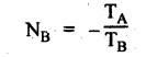
2. Algebraic (or Formula) Method
1. Tabulation Method
2. Algebraic (or Formula) Method


Theory of Machines: Unit II: Gears and Gear Trains : Tag: : Gears and Gear Trains - Theory of Machines - Velocity ratio for epicyclic gear train
Related Topics
Related Subjects

Theory of Machines
ME3491 4th semester Mechanical Dept | 2021 Regulation | 4th Semester Mechanical Dept 2021 Regulation