Theory of Machines: Unit I: Kinematics of Mechanisms
velocity analysis procedure by instantaneous centre method
Kinematics of Mechanisms - Theory of Machines
In this method, the velocity of links in a mechanism are determined using the following steps.
VELOCITY ANALYSIS PROCEDURE BY INSTANTANEOUS CENTRE METHOD
In
this method, the velocity of links in a mechanism are determined using the
following steps.
Step 1: Construction
of configuration diagram.
Step 2: Calculation of
velocity of input link (see Section 2.5)
Step 3: Locate the
required instantaneous centres (see Section 2.21)
Step 4: Determination
of velocity of various links
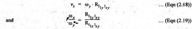
The velocity and
angular velocity of various links can be determined by measuring the distance
between various instantaneous centres and using the following relations.
Example 2.12
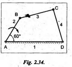
Locate all the instantaneous centres for a four-bar mechanism
shown in Fig.2.34. The lengths of various links are: AD = 125 mm; AB = 62.5 mm;
BC = CD = 75 mm. If the link AB rotates at a uniform speed of 10 rpm in
clockwise direction, find the angular velocity of the links BC and CD.
Given data:
AD
= 125 mm = 0.125 m; AB = 62.5 mm = 0.0625 m; BC = CD = 75 mm = 0.075 m; NAB
= 10 rpm (CW)
Solution: Instantaneous centre
method.
Procedure:
Step 1: Construction
of configuration diagram: First of all, draw the
configuration diagram, to some suitable scale (say, 1 cm = 25 mm), as shown in
Fig.2.35(a).
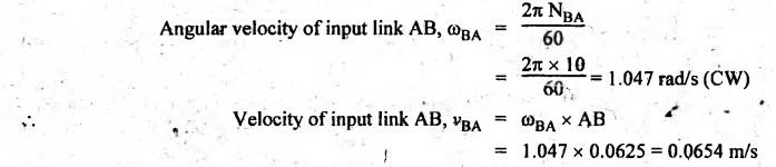
Step 2: Velocity of
input link:
Step 3: Locate the
required instantaneous centres:
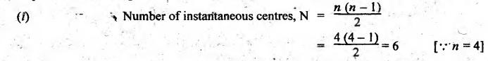
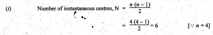
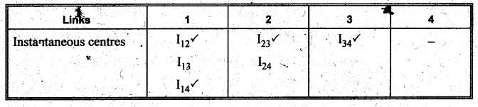
(ii)
Write down a list of all instantaneous centres in a book keeping table, as
shown below.
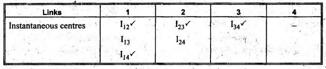
(iii)
Locate the fixed instantaneous centres (I12 and I14) and
permanent instantaneous centres (I23 and I34) by
inspection and tick mark it on the book keeping table.
(iv)
Locate the remaining, neither fixed nor permanent centres (I13 and I23),
by drawing a circle diagram. Mark points 1, 2, 3 and 4 on the circle equal to
the number of links in the mechanism, as shown in Fig.2.35(b).
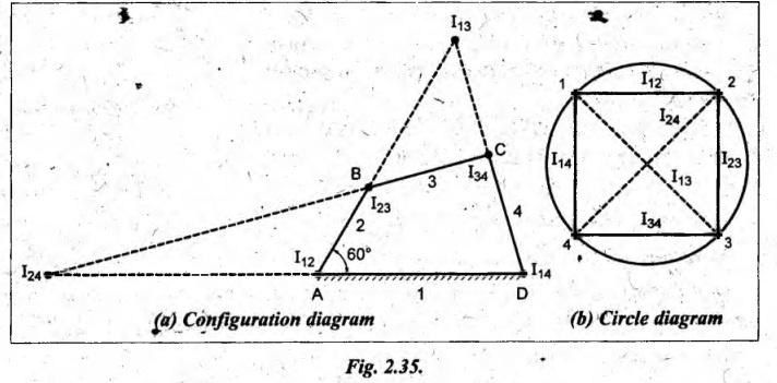
(v)
Join these points by solid lines such as 1-2, 2-3, 3-4 and 4-1 to indicate the
centres I12, I23, I34 and I14
respectively.
(vi)
The required other two instantaneous centres I13 and I24
are located by joining points 1 to 3 and 2 to 4 by dotted lines. Now all the
instantaneous centres are located, as shown in Fig.2.35(a).
Step 4: Determination
of velocity of various links:
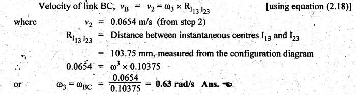
Angular velocity of link BC:
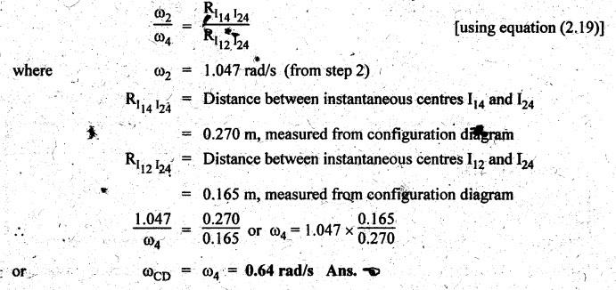
Angular velocity of link
CD:
Angular
velocity of link CD can be obtained by using the angular velocity ratio theorem
and is given by
Example 2.13
Locate all the instantaneous centres of the slider-crank
mechanism shown in Fig.2.36. Find:
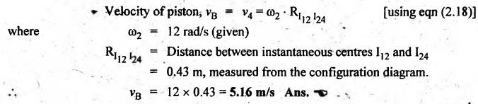
(i) velocity of piston, and
(ii) angular velocity of connecting rod.
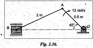
Given data:
OA
= 0.5 m; AB = 2 m; ![]() BOA = 45°; ωAO = 12 rad/s (CW)
BOA = 45°; ωAO = 12 rad/s (CW)
Solution: Instantaneous centre
method.
Procedure:
Step 1: Construction
of configuration diagram: First of all, draw the
configuration diagram, to some suitable scale (say, 1 cm = 0.2 m), as shown in
Fig.2.36(a).
Step 2: Velocity of
input link:
Velocity
of input link i.e., crank OA, vAO = ωAO × OA
=
12 × 0.5 = 6 m/s
Step 3: Locate the
required instantaneous centres:
(ii)
Write down a list of all instantaneous centres in a book keeping table, as
shown below.
(iii)
Locate the fixed instantaneous centres (I12 and I14) and
permanent instantaneous centres (I23 and I34) by inspection
and tick mark it on the book keeping table. Since the slider (link 4) moves on
straight line relative to link 1, therefore its instantaneous centre I14
will lie at infinity.
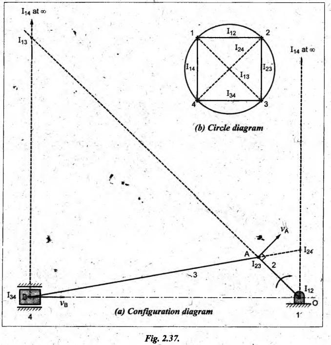
(iv)
Locate the remaining, neither fixed nor permanent centres (I13 and I24),
by drawing a circle diagram. Mark points 1, 2, 3 and 4 on the circle equal to
the number of links in the mechanism, as shown in Fig.2.37(b).
(v)
Join these points by solid lines 1-2, 2-3, 3-4 and 4-1 to indicate the centres
I12, I23, and I14 respectively.
(vi)
The required other two instantaneous centres I13 and I24
are located by joining points 1 to 3 and 2 to 4 by dotted lines. Now all the
instantaneous centres are located, as shown in Fig.2.37(a).
Step 4: Determination
of velocity of various links:
(i)
Velocity of piston:
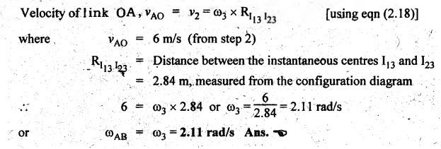
(ii) Angular velocity of connecting rod AB:
Theory of Machines: Unit I: Kinematics of Mechanisms : Tag: : Kinematics of Mechanisms - Theory of Machines - velocity analysis procedure by instantaneous centre method
Related Topics
Related Subjects

Theory of Machines
ME3491 4th semester Mechanical Dept | 2021 Regulation | 4th Semester Mechanical Dept 2021 Regulation