Theory of Machines: Unit I: Kinematics of Mechanisms
velocities in four-bar chain
Kinematics of Mechanisms - Theory of Machines
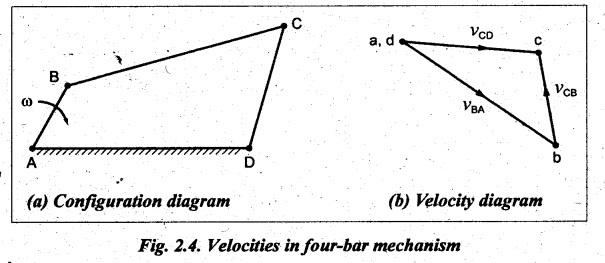
Fig.2.4(a) shows a four-bar chain ABCD in which AD is fixed and BC is the coupler.
VELOCITIES IN FOUR-BAR CHAIN
Fig.2.4(a)
shows a four-bar chain ABCD in which AD is fixed and BC is the coupler. AB is
the driver rotating at an angular speed of @ rad/s in the clockwise direction.
It is required to draw the velocity diagram of this configuration.
Procedure
Step 1: Configuration
diagram: First of all, draw the configuration
diagram, to some suitable scale, as shown in Fig.2.4(a).
Step 2: Velocity of
input link. When length of input link AB and its
angular velocity ωAB are known, then the velocity of the input link
(i.e., crank AB) is given by

Step 3: Velocity
diagram: Now draw the velocity diagram, as
shown in Fig.2.4(b), using the procedure given below.
1.
Since the link AD is fixed, the velocity of points A and D are zero and they
are represented by one point (a, d) in the velocity diagram.
2.
From point a, draw vector ab perpendicular to BA, to some suitable scale, to
represent the velocity of B with respect to A (i.e., vBА or vB)
such that
vector
ab = vBA = vB
3.
From point b, draw vector bc perpendicular CB to represent the velocity
of C with respect to B (i.e., vCB).
4.
Now from point d or a, draw vector de perpendicular to CD to
represent the velocity of C with respect to D (i.e., vCD
or vC).
5.
The vectors bc and dc intersect at point c. The vector dc
= vCD = vC.
Step 4: Velocity of
various links: By measurement of
vectors ac and bc, the velocities of link CD (vCD) and link
CB (vCB) can be determined.
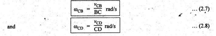
The
angular velocity of links BC and CD can be determined by using the relations
Theory of Machines: Unit I: Kinematics of Mechanisms : Tag: : Kinematics of Mechanisms - Theory of Machines - velocities in four-bar chain
Related Topics
Related Subjects

Theory of Machines
ME3491 4th semester Mechanical Dept | 2021 Regulation | 4th Semester Mechanical Dept 2021 Regulation