Engineering Mechanics: Unit II: Equilibrium of Rigid Bodies
Varignon's Theorem of Moments
with Solved Example Problems
Varignon's theorem states that "the algebraic sum of moments due to all forces acting on an object about any point is equal to the moment of their resultant about the same point"
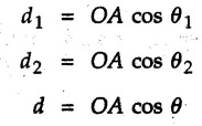
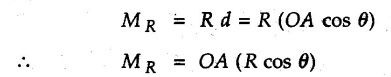
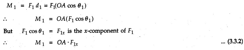
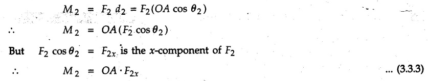
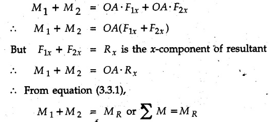
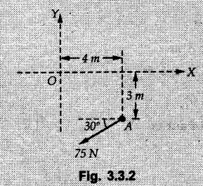
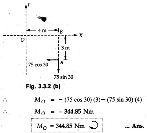
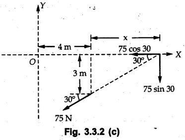
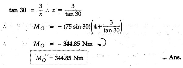
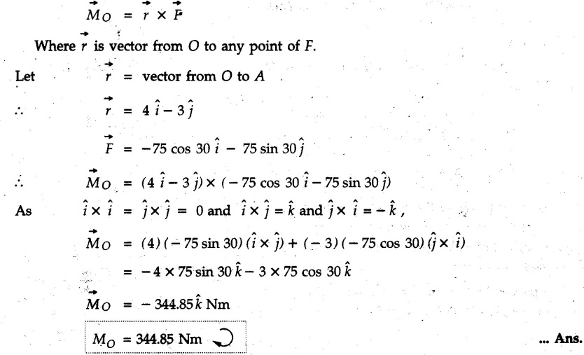
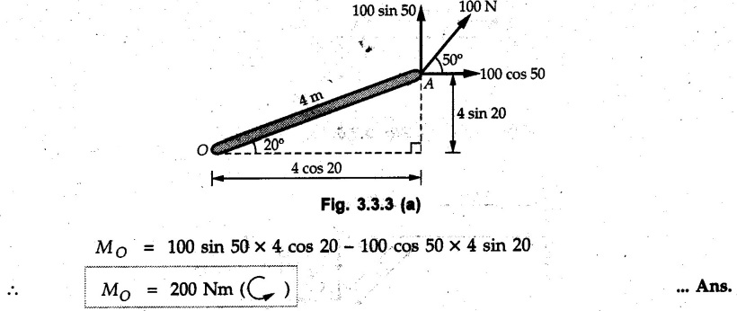
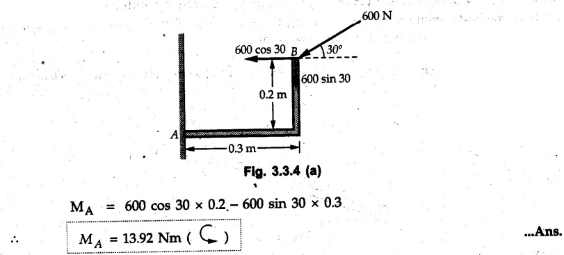
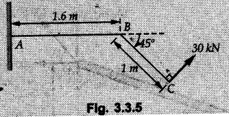
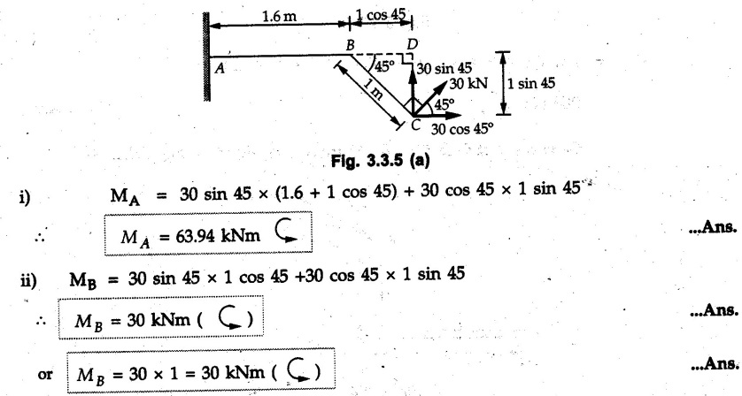
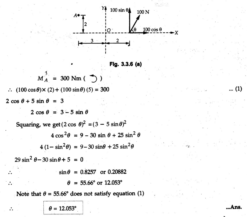
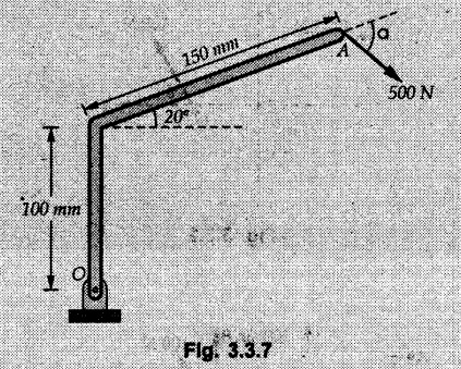
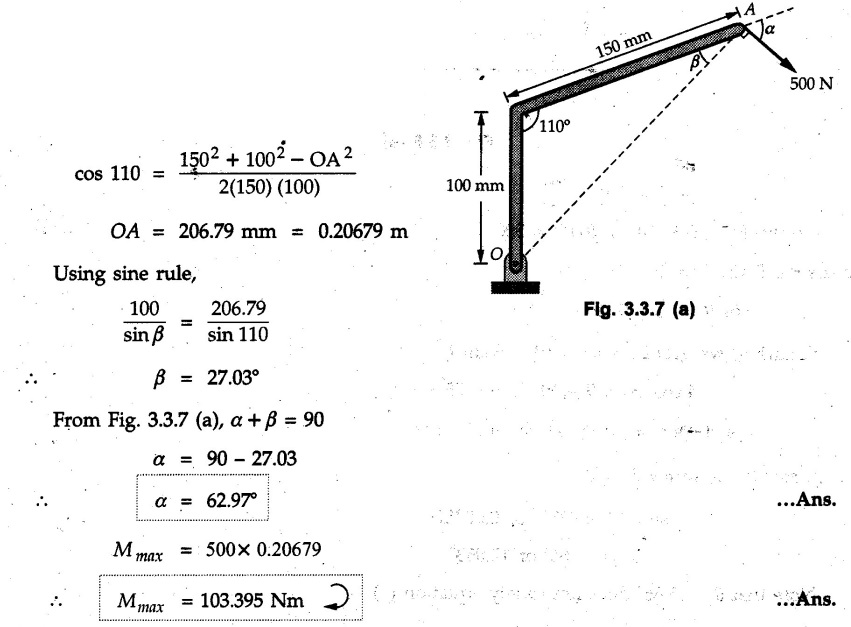
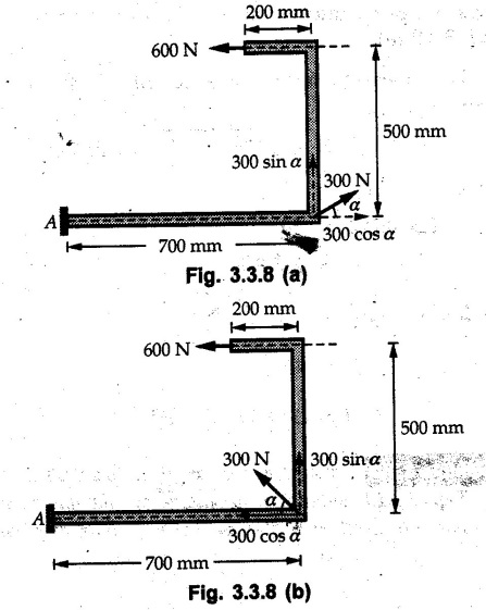
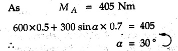
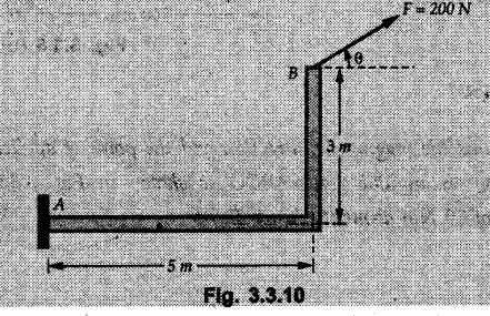
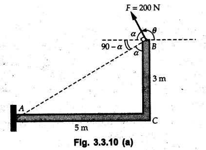
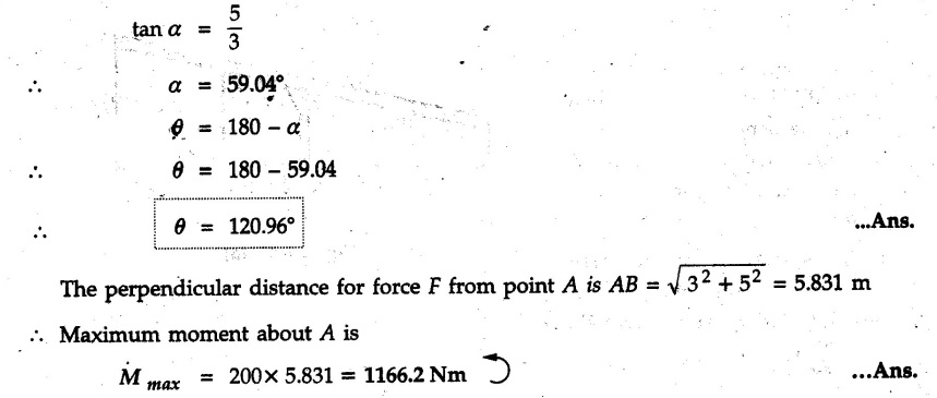
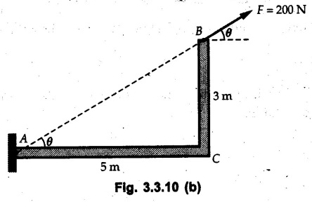
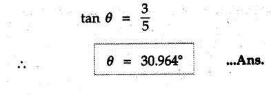
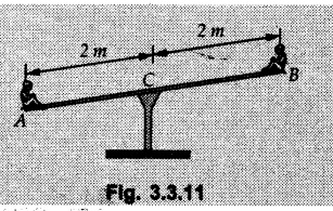
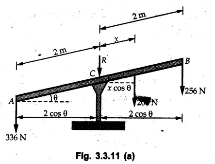
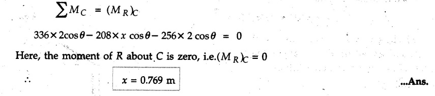
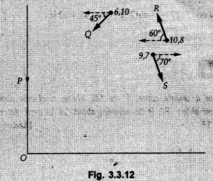
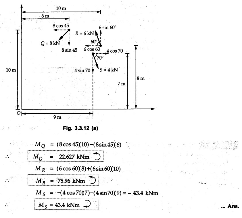
Varignon's Theorem of Moments • Varignon's theorem states that "the algebraic sum of moments due to all forces acting on an object about any point is equal to the moment of their resultant about the same point". • Consider two forces F1 and F2 making angles θ1 and θ2 respectively with X-axis and concurrent at the origin as shown in Fig. 3.3.1. • Let their resultant R make angle θ -with X-axis. The perpendicular distances of F1, F2 and R from point A are d1, d2 and d respectively. • The distances d1, d2 and d can be expressed in terms of OA as follows • The moment of R about A is • The x-component of resultant is • The moment of F1 about A is • The moment of F2 about A is • Adding equations (3.3.2) and (3.3.3) • Thus the algebraic sum of moments due to F1 and F2 about A is equal to the moment of their resultant about A. Example 3.3.1 Determine the moment of the 75 N force shown in Fig. 3.3.2 about O. Solution: The moment of force can be obtained using the following methods: i) By finding perpendicular distance and then using M = F d. ii) By resolving the given force into rectangular components at the given position and then adding the moments due to the two components. iii) By resolving the force on X-axis where the line of action intersects the X-axis. iv) By resolving the force on Y-axis where line of action intersects Y-axis. v) By using vector equation Method (i) To find perpendicular distance, draw perpendicular from O on line of action of force as shown in Fig. 3.3.2 (a). Method (ii) The components of force are as shown in Fig. 3.3.2 (b). Method (iii) When the force is resolved on X-axis, the moment produced by the x component about O becomes zero as its line of action passes through O. The perpendicular distance for y-component becomes 4 + x as shown in Fig. 3.3.2 (c). Where, Method (iv) When the force is resolved on Y-axis, the moment produced by y- component about O becomes zero and perpendicular distance for x-component is 3 + y as shown in Fig. 3.3.2 (d) where, Method (v) Using vector equation, Moment vector in positive z-direction represents anticlockwise sense of rotation. Here, Note: For understanding purpose this example is solved by different methods. Out of these methods, method (ii) i.e. resolving the given force into rectangular components and then adding the moments is most preferable. Example 3.3.2 Determine the moment of the 100 N force acting on the rod as shown in Fig. 3.3.3 about O. Solution: The required moment can be easily obtained by resolving the force into two components as shown in Fig. 3.3.3 (a). Example 3.3.3 Find the moment of force F = 600 N about A as shown in Fig. 3.3.4. Solution : Example 3.3.4 Find moment of force about A and B for the 30 kN force shown in Fig. 3.3.5. Solution : Here, 1 m is directly perpendicular distance between B and C. Example 3.3.5 The 100 N force shown in Fig. 3.3.6 produces anticlockwise moment of 300 Nm about A. Determine the angle θ (0 ≤ θ ≤ 90). Solution: Given Example 3.3.6 Determine the angle a for which the moment of the 500 N force shown in Fig. 3.3.7. is maximum about O. Also find the maximum moment. Solution: Moment of the 500 N force will be maximum about O when it is applied perpendicular to line OA as shown in Fig. 3.3.7 (a). Length OA can be obtained using cosine rule. Example 3.3.7 Determine the two values of a (0 ≤ α ≤ 180°) for which the combined moment of the two forces shown in Fig. 3.3.8 about A is 405 Nm anticlockwise. Solution: • The two orientations of the 300 N moment force for which about A be same are as shown in Fig. 3.3.8 (a) and Fig. 3.3.8 (b). In both cases the vertical component of the 300 N force is 300 sin α. • As the horizontal component 300 cos α in both cases does not produce moment about A and the 600 N force produces the same moment in both cases, the moment remains same. In the second case the angle with positive X-axis will be 180 – 30 = 150° Example 3.3.8 Determine the magnitude, direction and the point of application of the smallest force applied to the rectangular plate ABCD as shown in Fig. 3.3.9 which produces a clockwise moment of 50 Nm about the hinge E. Solution: As the force is required to be minumum, it must be applied at maximum distance from E, i.e. at point C. Also, the force must be perpendicular to line EC as shown in Fig. 3.3.9 (a). The perpendicular distance of Example 3.3.9 Determine the angle θ (0 ≤ θ ≤ 180°) for the force F = 200 N shown in Fig. 3.3.10, so that it produces a) Maximum moment about A and b) The minimum moment about A. Determine the maximum and minimum moment. Solution: a) To produce maximum moment about A, the force F = 200 N must be perpendicular to line AB as shown in Fig. 3.3.10 (a). Let α be the angle made by the force with horizontal as shown. from Δ ABC, b) The minimum moment of F will be obtained when F acts along the line AB as shown in Fig. 3.3.10 (b). From Δ ABC, As line of action of force passes through A, its moment about A is zero. Example 3.3.10 The weights of two children sitting at ends A and B of a seesaw are 336 N and 256 N respectively. Where should a third child of weight 208 N, sit so that the resultant of the weights of the three children will pass through point 'C'. Refer Fig. 3.3.11. Solution: • The anticlockwise moment produced by 336 N about C is larger than clockwise moment produced by 256 N about C. • The third child should sit to the right of C producing clockwise moment about C. Let, the third child be at distance 'x' from C. • Let angle made by seesaw be θ with horizontal. Then the perpendicular distances, from C will be as shown in Fig. 3.3.11 (a) for the three forces. • If resultant 'R' of the three forces passes through C using Varignon's theorem about C, It is important to note that, the angle of inclination of seesaw does not affect the calculations. Example 3.3.11 A system of four forces P, Q, R and S of magnitude 5 kN, 8 kN, 6 kN and 4 kN respectively acting on a body are shown in rectangular coordinates as shown in Fig. 3.3.9. Find the moments of the forces about the origin O. Also find the resultant moment of the forces about O. The distances are in metres. Solution: The moment of force P about O is zero as its line of action passes through O. The forces Q, R and S are resolved as shown in Fig. 3.3.12 (a). The perpendicular distances for the components are also shown.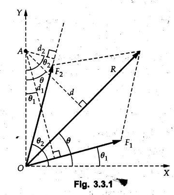

Solved Examples for Understanding

![]() is in negative z direction.
is in negative z direction.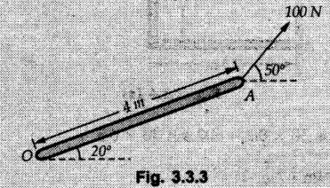

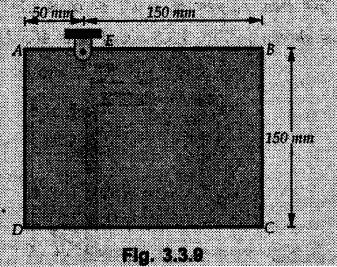
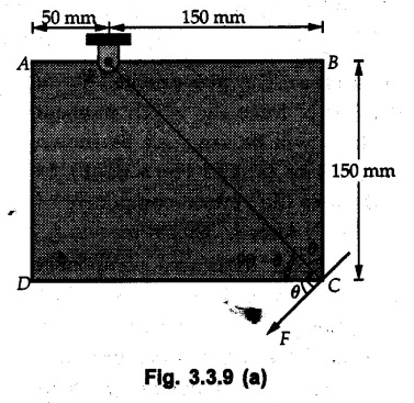
![]() from point E is
from point E is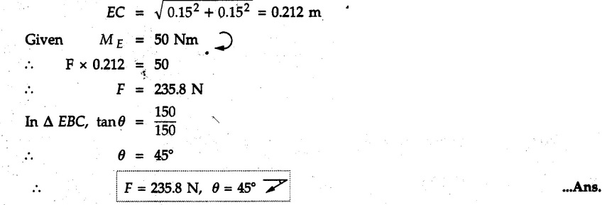

Engineering Mechanics: Unit II: Equilibrium of Rigid Bodies : Tag: : with Solved Example Problems - Varignon's Theorem of Moments
Related Topics
Related Subjects

Engineering Mechanics
ME3351 3rd semester civil, Mechanical Dept | 2021 Regulation | 3rd Semester Mechanical Dept 2021 Regulation