Basic Electrical and Electronics Engineering: Unit V: Measurements and Instrumentation
Types of Measurement Instruments
The PMMC instruments can be used for direct measurement only, and the induction type for alternating current measurements only.
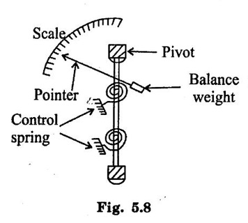
TYPES OF INSTRUMENTS (1) Permanent Magnet Moving Coil (PMMC) instruments. (2) Moving iron instruments. (3) Electrodynamometer instruments. (4) Thermal instruments (5) Induction instruments. (6) Electrostatic type instruments. (7) Rectifier type instruments. The PMMC instruments can be used for direct measurement only, and the induction type for alternating current measurements only. The moving iron(MI) and moving coil(MC) types both depend for their action upon the magnetic effect of current. The MI instruments can be used for either direct or alternating current measurements, and is the cheapest. Electrodynamometer type of instruments can be used both on a.c as well as on d.c. They are useful as "transfer instruments", as their calibration for both d.c and a.c is the same. The calibration for d.c and a.c is same for the thermal instruments also. They are particularly suited for a.c measurements. This is because, the deflection of the thermal instruments depends directly upon the heating effect of the alternating current, i.e., upon the rms value of the current. For the electrostatic instruments, the electrostatic principle is only directly applicable to voltage measurements. They have the advantage that, their power consumption is extremely small. The induction principle is more generally used for Watt- hour meters than for ammeters and voltmeters. These instruments are used either as ammeters or voltmeters and are suitable for d.c work only. PMMC instruments work on the principle that, when a current carrying conductor is placed in a magnetic field, a mechanical force acts on the conductor. The current carrying coil, placed in magnetic field is attached to the moving system. With the movement of the coil, the pointer moves over the scale to indicate the electrical quantity being measured. This type of movement is known as D' Arsonval movement. ● It consists of a light rectangular coil of many turns of fine wire wound on an aluminium former inside which is an iron core as shown in figure 5.7. The coil is delicately pivoted upon jewel bearings and is mounted between the poles of a permanent horse shoe magnet. ● Two soft-iron pole pieces are attached to these poles to concentrate the magnetic field. ● The current is led in to and out of the coils by means of two control hair- springs, one above and other below the coil, as shown in figure 5.8. These springs also provide the controlling torque. The damping torque is provided by eddy currents induced in the aluminium former as the coil moves from one position to another. When the instrument is connected in the circuit to measure current or voltage, the operating current flows through the coil. Since the current carrying coil is placed in the magnetic field of the permanent magnet, a mechanical torque acts on it. As a result of this torque, the pointer attached to the moving system moves in clockwise direction over the graduated scale to indicate the value of current or voltage being measured. This type of instruments can be used to measure direct current only. This is because, since the direction of the field of permanent magnet is same, the deflecting torque also gets reversed, when the current in the coil reverses. Consequently, the pointer will try to deflect below zero. Deflection in the reverse direction can be prevented by a "stop" spring. The magnetic field in the air gap is radial due to the presence of soft iron core. Thus, the conductors of the coil will move at right angles to the field. When the current is passed through the coil, forces act on its both sides which produce the deflecting torque. Let, B = flux density, Wb/m2 l = length or depth of coil, m b = breadth of the coil. N = no. of turns of the coil If a current of 'I' Amperes flows in the coil, then the force acting on each coil side is given by, Force on each coil side, F = BIlN Newtons. Deflecting torque, Td = Force × perpendicular distance = (BIlN) × b Deflecting torque, Td = BINA Newton metre. Where, A = l × b, the area of the coil in m2. Thus, Td ∝ I The instrument is spring controlled so that, Tc ∝ θ The pointer will comes to rest at a position, where Td = Tc Therefore, θ ∝ I Thus, deflecting torque is directly proportional to the current passing through the coil. Hence, such instruments have uniform scale. (a) Uniform scale.ie, evenly divided scale. (b) Very effective eddy current damping. (c) High efficiency. (d) Require little power for their operation. (e) No hysteresis loss (as the magnetic field is constant). (f) External stray fields have little effects on the readings (as the operating magnetic field is very strong). (g) Very accurate and reliable. (a) Cannot be used for a.c measurements. (b) More expensive (about 50%) than the moving iron instruments because of their accurate design. (c) Some errors are caused due to variations (with time or temperature) either in the strength of permanent magnet or in the control spring. (a) Used in the measurement of direct currents and voltages. (b) Used in d.c galvanometers to detect small currents. (c) In Ballistic galvanometers used for measuring changes of magnetic flux linkages. Moving Iron (M.I) instruments are mainly used for the measurement of alternating currents and voltages, though it can also be used for d.c measurements, these instruments are more commonly used in laboratories at power frequencies. The general principle of a M.I instrument can be explained under; Let a plate or vane of soft iron or of high permeability steel forms the moving element of the system. The iron vane is situated so as, it can move in a magnetic field produced by a stationary coil. The coil is excited by the current or voltage under measurement. When the coil is excited, it becomes an electromagnet and the iron vane moves in such a way so as to increase the flux of the electromagnet. Thus, the vane tries to occupy a position of minimum reluctance. Thus, the force produced is always in such a direction so as to increase the inductance of the coil. There are two types of Moving- iron instruments. i. Attraction type ii. Repulsion type In this type of instrument, a single soft iron vane (moving iron) is mounted on the spindle, and is attracted towards the coil when operating current flows through it. The construction of the attraction type instrument is shown in the Figure 1.99 It consists of a fixed coil C and moving iron piece D. The coil is flat and has a narrow slot like opening. The moving iron is a flat disc which eccentrically mounted on the spindle. The spindle is supported between the jewel bearings. When current flows in the coil, the soft-iron piece is attracted towards the coil and the movement causes pointer to move across the scale. The pointer will come to rest at a position where deflecting torque is equal to the controlling torque. The controlling torque is provided by the springs but gravity control may also be used for vertically mounted panel type instruments. The damping torque is provided by the air friction. A light aluminium piston is attached to the moving system. It moves in a fixed chamber. The chamber is closed at one end. It can also provided with the help of van attached to the moving system. The operating magnetic field in moving iron instruments is very weak. Hence eddy current damping is not used since it require a permanent magnet which would affect or distort the operating field. The force F, pulling the soft -iron piece inwards is directly proportional to; a) Field strength H, produced by the coil. b) pole strength 'm' developed in the iron piece which again depends on H.. F ∝ mH F ∝ H2 Since, m ∝ H, Instantaneous deflecting torque, Td ∝ F ∝ H2 Also, the field strength H = μ i If the permeability(μ) of the iron is assumed constant, Then, H ∝ i Where, i → instantaneous coil current, Ampere So, Instantaneous deflecting torque Td ∝ H2 ∝ i2 …… (1) Since the instrument is spring controlled, the controlling torque is given by Tc ∝ deflection of the disc, θ …… (2) From equations (1) & (2) θ ∝ i2 In the steady position of deflection, Td = Tc θ ∝ i2 r.m.s. value. Since the deflection is proportional to the square of coil current, the scale of such instruments is not graduated uniformly (being crowded in the beginning and spread out near the finishing end of the scale). If current in the coil is reversed, the direction of magnetic field also reverses and so does the magnetism produce in the soft iron piece. Hence, the direction of the deflecting torque remains unchanged. i.e., In the reverse direction, the current I becomes (-1) and hence I2 becomes positive. Therefore the deflection will be positive irrespective of deflection coil current polarity. For this reason, such instruments can be used for both d.c. and a.c. measurements. In this two soft iron vanes are used; one fixed and attached with the stationary coil, while the other is movable (moving iron), and mounted on the spindle of the instrument. When operating current flows through the coil, the two vanes are magnetized, developing similar polarity at the same ends. Consequently, repulsion takes place between the vanes and the movable vane causes the pointer to move over the scale. There are Two types in repulsion type instrument. i.radial vane type: vanes are radial strips of iron. ii.co-axial vane type: vanes are sections of coaxial cylinders. Deflecting Torque: The deflecting torque result due to the repulsion between the similarly changed iron pieces. If the two pieces develop pole strength m1 and m2 respectively, then Instantaneous deflecting torque ∝ repulsive force ∝ m1 m2 Since, pole strengths developed are proportional to H. Instantaneous deflecting torque. Тd ∝ H2 Assuming constant permeability H ∝ current I through coil Deflecting torque Td ∝ I2 Controlling torque provided by spring Tc ∝ θ In the steady position of deflection, Td = Tc Θ ∝ I2 ∝ I2 (for d.c) ∝ Ir.m.s (for a.c) Since deflection θ is proportional to square of current through the coil therefore scale of such instruments is non-uniform; being crowded in the beginning. However, scale of such instruments can be made uniform by using torque shaped iron pieces.1. Permanant Mmagnet Moving Coil (PMMC) Instruments
Principle:
Construction:-
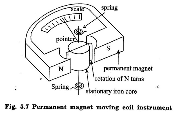
Working:
Deflecting torque equation:
Advantages
Disadvantages:
Applications:
2. Moving Iron Instruments
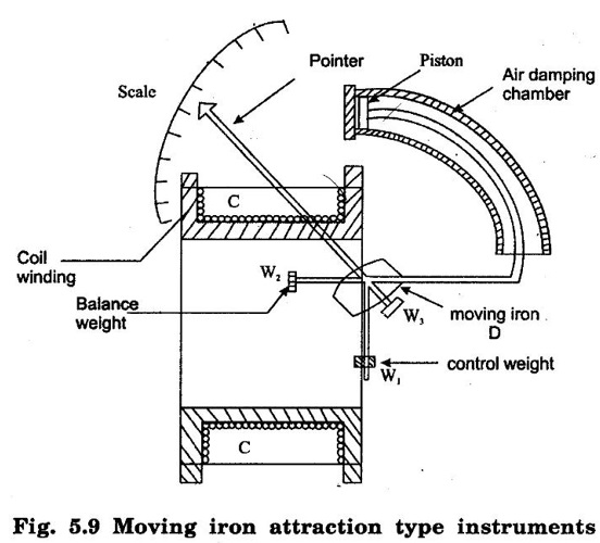
i. Attraction type:-
Deflecting torque equation
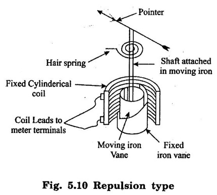
ii. Repulsion type:
Basic Electrical and Electronics Engineering: Unit V: Measurements and Instrumentation : Tag: : - Types of Measurement Instruments
Related Topics
Related Subjects

Basic Electrical and Electronics Engineering
BE3251 2nd semester Mechanical Dept | 2021 Regulation | 2nd Semester Mechanical Dept 2021 Regulation

Basic Electrical and Electronics Engineering
BE3251 2nd Semester CSE Dept 2021 | Regulation | 2nd Semester CSE Dept 2021 Regulation