Engineering Graphics: Unit IV (a): Sections of Solids
Types of Cutting Planes
Sections of Solids | Engineering Graphics (EG)
The shape of the sectioned surface depends upon the orientation of the solid with respect to the reference planes and the orientation of the cutting plane with respect to the principal planes of projections.
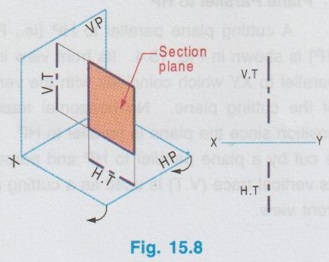
TYPES OF CUTTING PLANES The shape of the sectioned surface depends upon the orientation of the solid with respect to the reference planes and the orientation of the cutting plane with respect to the principal planes of projections. Some of the orientation of the cutting planes are: 1. Plane parallel to HP 2. Plane parallel to VP 4. Auxiliary Inclined plane 4. Auxiliary Vertical plane 5. Profile plane 6. Oblique plane A cutting plane parallel to HP (ie., Perpendicular to VP) is shown in Fig. 15.4. Its front view is a straight line, parallel to XY which coincides with the vertical trace (V.T) of the cutting plane. No horizontal trace (H.T) for this position since the plane is parallel to HP. Hence if a solid is cut by a plane parallel to HP and perpendicular to VP, its vertical trace (V.T) is used as a cutting plane line in the front view. A cutting plane parallel to VP (ie., Perpendicular to HP) is shown in Fig. 15.5. Its topview is a straight line, parallel to XY which coincides with the Horizontal trace (H.T) of the cutting plane. No vertical trace for this position liquo fol since the plane is parallel to VP. Hence if a solid is cut by a plane parallel to VP and perpendicular to HP, its horizontal trace (H.T) is used as a cutting plane line in the top view. A plane perpendicular to VP and inclined at an angle θ to HP is known as auxiliary inclined plane as shown in Fig. 15.6. Its front view is a straight line inclined at θ to XY which coincides with its vertical trace V.T. The horizontal trace (H.T) of the section plane is a line perpendicular to XY. Hence if a solid is cut by a plane perpendicular to VP and inclined to HP at θ, its vertical trace (V.T) inclined at θ to XY line is used as a cutting plane line in the front view. The cutting plane perpendicular to HP and inclined at an angle ϕ to VP is known as auxiliary vertical plane as shown in Fig. 15.7. Its topview is a straight line inclined at an angle ϕ to XY line wich coincides with its Horizontal trace (H.T). The vertical trace (V.T) of the section plane is a line perpendicular to XY line as shown in Fig. Hence if a solid is cut by a plane, perpendicular to HP and inclined at an angle ϕ to VP, its horizontal trace (H.T) inclined at ϕ to XY line is used as a cutting plane line in the top view. The plane perpendicular to both HP and VP is known as Profile plane as shown in Fig. 15.8. Its topview and front view are straight lines which coincides with its horizontal trace (H.T) and vertical trace (V.T) respectively as shown in Fig. 15.8. Hence if a solid is cut by a profile plane, both horizontal and vertical traces (both H.T and V.T) are used as a cutting plane line in the front view and top view respectively. A plane which is inclined to both HP and VP is known as oblique plane. Its front view and top view are straight lines inclined at θ to HP and ϕ to VP which coincides with its vertical trace and horizontal trace respectively. Hence both H.T and V.T, inclined with reference line are used as a cutting plane line in the front view and top view respectively. Note : Study on oblique planes of section planes are not presented in this book.1. Plane Parallel to HP
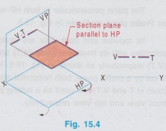
2. Plane Parallel to VP
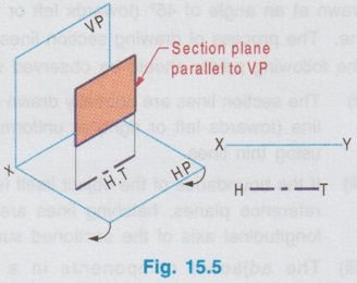
3. Auxiliary Inclined Plane
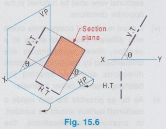
4. Auxiliary Vertical Plane
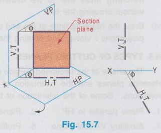
5. Profile Plane
6. Oblique plane
Engineering Graphics: Unit IV (a): Sections of Solids : Tag: : Sections of Solids | Engineering Graphics (EG) - Types of Cutting Planes
Related Topics
Related Subjects

Engineering Graphics
GE3251 eg 2nd semester | 2021 Regulation | 2nd Semester Common to all Dept 2021 Regulation