Manufacturing Technology: Unit I: Mechanics of Metal Cutting
Types of chips
Mechanics of Metal Cutting - Manufacturing Technology
The various types of chips are formed during metal cutting. The type of chip formed during metal cutting depends upon the machining condition and material to be cut.
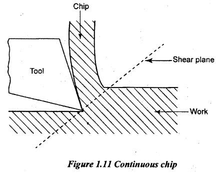
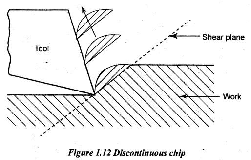
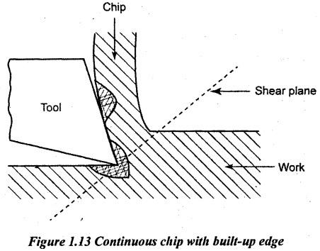
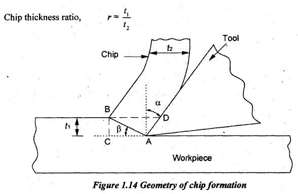
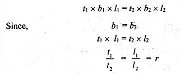
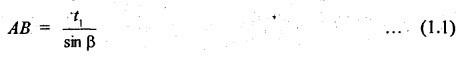
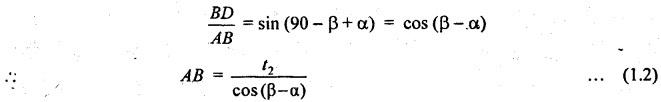
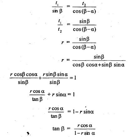
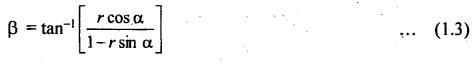
TYPES OF CHIPS The various types of chips are formed during metal cutting. The type of chip formed during metal cutting depends upon the machining condition and material to be cut. Generally, there are following three types of chips.. 1. Continuous chip 2. Discontinuous chip 3. Continuous chip with build-up edge. During cutting of ductile material, a continuous ribbon-like chip is produced due to the pressure of the tool cutting edge in compression and shear. These types of chips are in the form of a long coil and have the same thickness throughout the length. This type of chip is most required, since it gives the advantage of good surface finish, improving the tool life and less power consumption. However, the chip disposal is not easy and the surface finish of the finished work gets affected. The following conditions favour the formation of continuous chips. • Ductile material such as low carbon steel, aluminium, copper etc. • Smaller depth of cut • High cutting speed • Large rake angle • Sharp cutting edge • Proper cutting fluid • Low friction between tool face and chip interface. Discontinuous chips as shown in Figure 1.12 are produced while machining brittle materials such as grey cast iron, bronze, high carbon steel at low cutting speeds without fluid when the friction exists between tool and chip interface. During machining, the brittle material lacks its ductility which is necessary for the plastic chip formation. But, it is less. It results in the formation of the discontinuous chip. In the case of continuous chip, the shearing occurs at the head of the cutting tool continuously without fracture whereas in discontinuous chip formation, the rupture occurs intermittently which produces segments of chips. Handling of these chips is easier and it can be easily disposed- off since they are having small lengths. Also, it will not spoil the finished work surface as they do not interfere. The following conditions favour the formation of discontinuous chips • Machining of brittle material • Small rake angle • Higher depth of cut • Low cutting speeds • Excess cutting fluid • Cutting ductile material at very low feeds with small rake angle of the tool. During cutting process, the interface temperature and pressure are quite high and also high friction between tool-chip interface. It causes the chip material to Weld itself to the tool face near the nose as shown in Figure 1.13 is called “built-up edge”. The formation of a built-up edge in the continuous chip is a transient and not stable phenomenon. The accumulated built-up of chip material will then break away, part adhering to the underside of the chip and part to the workpiece. Thus, the process gives a rise to the poor surface finish on the machined surface and accelerated wears on the tool face. However, this type of chips has some advantages. The one important favour of it is that the rake face of the tool is protected from wears due to moving chips and the action of heat. It may result increased tool life. The following conditions favour the formation of continuous chips with built-up edge • Low cutting speed • Small rake angle • Coarse feed • Strong adhesion between chip and tool interface • Insufficient cutting fluid • Large uncut thickness. The following variables are influencing in producing the type of chip: (i) Mechanical properties of material to be cut in particular ductility and brittleness (ii) Depth of cut (iii) Various angles of tool, especially rake angle (iv) Cutting speed (v) Feed rake (vi) Type of cutting fluid (vii) Machining temperature of cutting region (viii) Surface finish required on workpiece (ix) The coefficient of friction between chip and tool interface. Generally, the chip thickness after cutting is larger than the chip thickness before cutting the workpiece. Also, the metal prior to being cut is much longer than the chip which is removed. Let t1, b1 and ll - Thickness, width and length of chip before cutting. t2, b2 and l2 - Thickness, width and length of chip after cutting. The ratio of chip thickness before cutting to the chip thickness after cutting is called chip thickness ratio. It is denoted by r. The chip thickness ratio is always less than one. A ratio 1:2 yields good results. The reciprocal of chip thickness ratio is called chip reduction coefficient. It is denoted by the letter k. There is no change in volume when the metal is cut. Volume of metal to be removed = Volume of chip. The chip thickness ratio is used to measure shear angle (β) as follows. From right angle triangle ABC in Figure 1.14, From right angle triangle ABD, where α = rake angle Equating the equation (1.1) and (1.2), From the above relation shear angle,1. Continuous Chip
2. Discontinuous or Segmental Chip
3. Continuous Chip with Built-Up Edge
4. Geometry of Chip Formation

Manufacturing Technology: Unit I: Mechanics of Metal Cutting : Tag: : Mechanics of Metal Cutting - Manufacturing Technology - Types of chips
Related Topics
Related Subjects

Manufacturing Technology
ME3493 4th semester Mechanical Dept | 2021 Regulation | 4th Semester Mechanical Dept 2021 Regulation