Theory of Machines: Unit III: Friction in Machine Elements
Types of belt drives
Friction in Machine Elements - Theory of Machines
The belt drives can be broadly classified as shown in Fig.8.5.
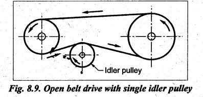
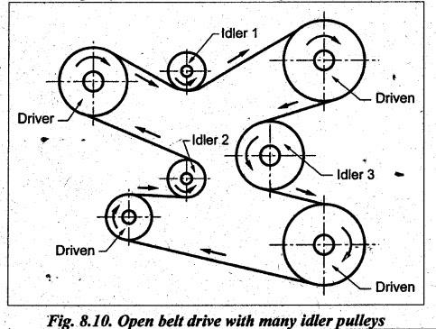
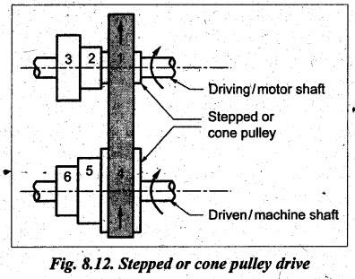
TYPES OF BELT DRIVES • The belt drives can be broadly classified as shown in Fig.8.5. • In parallel drives, the axes of rotation of the driving and driven pulleys are parallel. On the other hand, in angular drives, the axes of rotation of the driving and driven pulleys are either at right angles or intersecting when produced. • Depending on the requirement, belts can be arranged in different ways. The different types of belt arrangement and their applications are tabulated, as shown in Table 8.3. Table 8.3. Types of flat belt drives and their applications 1. Open Belt Drive • The open belt drive is used with shafts arranged parallel and rotating in same direction, as shown in Fig.8.6. • Driver and driven: One of the two connected pulleys (usually coupled with motor shaft) that drives the belt is called the driver pulley or the driver. The other pulley, which is driven by the driver, is called the driven pulley or the driven or the follower. • It may be noted that unlike in gear drives, it is not necessary for the driver pulley to be smaller than driven pulley. This is because the belt drive can be used either as a speed reducer or for increasing the speed. • Right and slack sides: In Fig.8.6(a), driver pulley pulls the belt from one side (lower side CD) and delivers it to other side (upper side AB). So tension in the pulled side (i.e., side CD) will be more than the other side (ie., side AB). Because of more tension on side CD, the side CD is known as tight side whereas the side AB (because of lesser tension) is known as slack side. • In Fig.8.6(b), it may be noted that the driver pulley is smaller than the driven pulley. Also the pulled side (i.e., side AB) of the belt is the tight side and the right side of the is the slack side. 2. Crossed (or Twisted) Belt Drive • The crossed or twist belt drive is used with shafts arranged parallel and rotating in the opposite direction, as shown in Fig.8.7. • Like in open belt drive, in Fig.8.7, driver pulley pulls the belt from one side (ie., side CD) and delivers it to other side (i.e., side AB). So tension in the pulled side (side CD) will be more than the other side (side AB). The side CD of the belt is the tight side whereas the side AB of the belt (because of lesser tension) is the slack side. 3. Compound Belt Drive • A compound belt drive is used when power is transmitted from one shaft to another through a number of pulleys, as shown in Fig.8.8. • Usually the compound belt drive is used to connect shafts with large centre distance. • In Fig.8.8, the pulleys 2 and 3 are known as intermediate shafts or countershaft pulleys. Countershaft pulleys are used where very high speed reduction is required. 4. Open Belt Drive with Idler Pulleys (a) Open belt drive with single idler pulley • A belt drive with an idler pulley is used with shafts arranged parallet and when an open belt drive cannot be used due to small angle of contact on the smaller pulley, as shown in Fig.8.9. • On account of constant use of belt, it gets permanently stretched. This reduces the initial tension in the belt and increases the slip between the belt and pulley. In that case idler pulley is used to maintain the tension in the belt. • The idler pulley, also known as jockey pulley, is a tensioner that helps provide the right level of tension on the belt and ensure correct operation. • An idler pulley is also a guide pulley on long stretches of belts that helps them from coming off the main pulley. (b) Open belt drive with many idler pulleys • A belt drive with many idler pulleys is used when it is desired to transmit motion from one shaft to several parallel shafts, as shown in Fig.8.10. 6. Quarter Twist (or Quarter Turn) Drive • The quarter turmbelt drive is used with shafts arranged at right angles and rotating in one definite direction, as shown in Fig.8.11. • In this drive, the axes of the driving and driven shafts are non-intersecting but at right angle to each other. • In the drive shown in Fig.8.11, the driving pulley must rotate in anticlockwise direction. If the direction is reversed the belt will run off the pulleys. 9. Stepped (or Cone) Pulley Drive • A stepped or cone pulley drive is used for changing the speed of the driven shaft while the main or driving shafts runs at constant speed, as shown in Fig.8.12. • Stepped pulleys are used for varying the speed of the driven/machine shaft. The speed of the driven shaft can be varied gradually by shifting the belt from one part of the steps to the other. • In Fig.8.12, two cone pulleys are used. One cone pulley is keyed to driving shaft and the second cone pulley is keyed to the driven shaft. When the belt is on steps (1) and (4), the speed of driven shaft is lowest. To increase the speed of driven shaft, the belt is shifted to steps (2) and (5). For further increase in speed of driven shaft, belt is shifted to steps (3) and (6). 10. Fast and Loose Pulley Drive • A fast and loose pulley drive is used when the driven or machine shaft is to be started or stopped whenever desired without interfering with the driving shaft, as shown in Fig.8.13. • In a factory or workshop where several machines are driven from a single driving shaft. The shaft of each machine has two pulleys: fast and loose pulleys. The fast pulley is keyed with machine shaft whereas the loose pulley has a bush in its hole and is free to rotate on the machine shaft. The belt actuator/shifter is used to push the belt between loose pulley and fast pulley, as per the requirement. • When the belt is shifted to fast pulley, the power is transmitted to the machine. But when the machine is to be stopped without stoppin the other machines, the belt is shifted to its loose pulley with the help of belt actuator. In that position, belt will rotate the loose pulley but the machine shaft will not rotate because the loose pulley is free to rotate on it. Note Crowning of pulley: The rim of the pulley is given camber (i.e., taper) on the surface, as shown in Fig.8.14. The camber is called crowning. Due to crowning, the belt will not slip off the pulley when it rotates. Because the belt has tendency to move to the farthest distance from the pulley axis due to centrifugal force, and this is possible only if the belt is in the middle of the pulley.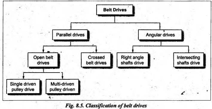


Theory of Machines: Unit III: Friction in Machine Elements : Tag: : Friction in Machine Elements - Theory of Machines - Types of belt drives
Related Topics
Related Subjects

Theory of Machines
ME3491 4th semester Mechanical Dept | 2021 Regulation | 4th Semester Mechanical Dept 2021 Regulation