Manufacturing Technology: Unit I: Mechanics of Metal Cutting
Two mark questions and answers
Mechanics of Metal Cutting - Manufacturing Technology
Two mark questions and answers: Mechanics of Metal Cutting - Manufacturing Technology
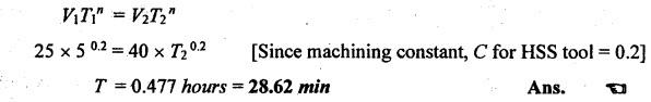
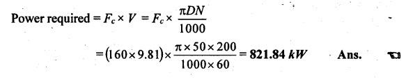
TWO MARK QUESTIONS AND ANSWERS 1. Classify the process of metal shaping. (i) Non-cutting shaping process (ii) Cutting shaping process. 2. Explain the non-cutting shaping process. The metal is shaped under the action of force, heat or both. Since there is no cutting of metal, the chip formation will not be there. So, it is called non-cutting shaping process. Example: Forging, drawing, rolling, spinning etc. 3. Explain the cutting shaping process. The required shape of metal is obtained by removing the unwanted material from the workpiece in the form of chips is called cutting shaping process. Example: Turning, drilling, milling, boring etc. 4. List the physical functions of a machine tool in machining. A machine tool is a machine for shaping, machining metal or other rigid materials by cutting, boring, grinding, shearing or other forms of deformation. Machine tools employ some sort of tool that does the cutting or shaping. All machine tools have some forms of constraining the workpiece and provide a guided movement of the parts of the machine. 5. What are all the different types of cutting tool? a) Single point cutting tool b) Multiple point cutting tool. 6. Mention the various parts of the single point cutting tool. 1) Shank 2) Face 3) Flank 4) Base 5) Nose 6) Cutting edge. 7. What is tool signature? The various angles of tools are mentioned in a numerical number in a particular order. This order is known as tool signature. 8. What do you understand by cutting tool signature? The various angles of tools are mentioned in a numerical number in a particular order. This order is known as tool signature. Example: A tool having 8, 8, 5, 5, 6, 6, and 1 as signature in ASA system will have the following angles. Back rake angle = 8° Side rake angle = 8° End relief angle = 5° Side relief angle = 5° End cutting edge angle = 6° Side cutting edge = 6° Nose radius = 1 mm. 9. Name the seven elements of tool geometry for a single point cutting tool. (i) Back rake angle (ii) Side rake angle (iii) End relief angle (iv) Side relief angle (v) End cutting edge angle (vi) Side cutting edge, and (vii) Nose radius. 10. Briefly explain the effect of rake angle during cutting. Rake angle has a great effect on the cutting forces. Increasing and decreasing or keeping the rake angle negative and positive, the cutting force and power increases and decreases respectively. A higher value of rake angle weakens the cutting edge. Back rake angle: The size of the angle depends upon the material to be machined. When the back rake angle increases, the cutting force decreases because of small shear strain. If the material is softer, the greater angle should be given whereas the material is harder, the smaller angle will be enough. Side rake angle: During cutting process, the chip curling or the amount of chip bend depends on the side rake angle. If the side rake angle is larger, the amount of power required to cut and bend the chip will decrease. Hence, it produces a better surface finish. 11. What is rake angle? What is the effect of nose radius in tools? The angle between the tool face and the line parallel to the base of the tool is known as side rake angle. It is used to control chip flow. The effects of the nose radius are as follows: 1. Greater nose radius removes the previous marking formed by shearing action and it obtains better surface finish. 2. It increases the strength of cutting edge. 3. Heat accumulation is reduced. 4. Cutting force is reduced slightly. 12. How does rake angle affect the life of the cutting tool? Higher rake angles produce the tool under higher tension forces and lighter compressive forces. Similarly, negative rakes produce greater compression and less tension. Higher rakes also concentrate the heat of the cut in a much smaller mass at the cutting edge which leads to occur thermal failure. 13. What is clearance angle and mention the types? These are the slopes ground downwards from the cutting edges. The clearance angle can be classified into two types. (i) Side relief angle (ii) End relief angle. 14. Explain the nose radius. It is the joining of side and end cutting edges by means of small radius in order increase the tool life and better surface finish on the workpiece. 15. Why can relief/clearance angles never be zero or negative? If relief/clearance angles are zero or negative, the tool will rub against the job. So, the tool will get overheated and cutting is not proper. So, a poor surface finish is obtained. 16. What do you understand by negative rake angle? The slope given away from the cutting edge is called negative rake angle. 17. What are the advantages of increasing nose radius? If the nose radius increases, the strength of cutting tool is increased and it is used on castings and cast iron where the cuts are interrupted. 18. State any two situations where positive rake angle is recommended during turning. (i) To machine the work hardened materials (ii) To machine low strength ferrous and non-ferrous metals (iii) To turn the long shaft of smaller diameters (iv) To machine the metal having lesser recommended cutting speeds (v) To machine the workpiece using small machine tools with low horsepower. 19. When will the negative rake angles be used? (i) To machine high strength alloys. (ii) When the machine tools are more rigid. (iii) Where the feed rates are high. (iv) To give heavy and interrupted cuts. 20. Name the factors that contribute to poor surface finish in cutting. (a) Cutting speed (b) Feed (c) Depth of cut. 21. Classify the types of metal cutting process. (a) Orthogonal cutting process (Two dimensional cutting) (b) Oblique cutting process (Three dimensional cutting). 22. What is orthogonal cutting? The cutting edge of tool is perpendicular to the workpiece axis. 23. Sketch the orthogonal cutting. 24. Give two examples for orthogonal cutting. Turning, facing, thread cutting and parting off. 25. Define oblique cutting. The cutting edge is inclined at an acute angle with normal to the cutting velocity vector is called oblique cutting. The analysis of the oblique cutting is more complex. In actual machining, cutting operations such as turning, milling etc. are oblique cutting. 26. Compare orthogonal and oblique cutting. 27. Write a short note on Heat zones in cutting. The heat is generated in three regions such as shear zone, tool-work interface region and tool-work interface region. (i) Shear zone: The zone which is affected by the energy required to shear the chip or to separate the chip and work is called shear zone. So, the energy required to shear the chip is the ́source of heat. Nearly, 80-85% of heat is generated in this region. (ii) Chip-tool interface region: In this region, the energy required to overcome the friction completely is the source. of heat. Here, some plastic deformation also takes place. The heat generation is in the range of 15-20%. (iii) Tool-work interface region: In this region, the energy required to overcome the rubbing friction between flank face of the tool and workpiece is the source of heat. In this region, the heat generation is in the range of 1-3%. 28. What is shear plane? The material of workpiece is stressed beyond its yield point under the compressive force. It causes the material to deform plastically and shear off. The plastic flow takes place in a localized region called shear plane. 29. What is cutting force? The sheared material begins to flow along the cutting tool face in the form of small pieces. The compressive force applied to form the chip is called cutting force. 30. What is chip? The sheared material begins to flow along the cutting tool face in the form of small pieces is called chip. Chips are mainly classified into three types. 31.Name and briefly describe the four types of chips that occur in metal cutting operations. (a) Continuous chip (b) Discontinuous chip (c) Continuous chip with build-up edge (d) Serrated chips or non-homogeneous Strain-Chip. (a) Continuous chip: During cutting of ductile material, a continuous ribbon-like chip is produced due to the pressure of the tool cutting edge in compression and shear. These types of chips are in the form of a long coil and have the same thickness throughout the length. (b) Discontinuous or segmental chip: Discontinuous chips are produced while machining brittle materials such as grey cast iron, bronze, high carbon steel at low cutting speeds without fluid when the friction exists. between tool and chip interface. (c) Continuous chip with built-up edge: During cutting process, the interface temperature and pressure are quite high and also high friction between tool-chip interface. It causes the chip material to weld itself to the tool face near the nose is called "built-up edge". (d) Serrated chips or Non-homogeneous Strain-Chip: This chip has a saw tooth appearance due to an alternating large zone of high shear strain followed by a small zone of low shear strain. Due to this cyclic chip formation, it becomes semi-continuous. This type of chip is produced while machining hard alloys like titanium which suffer a marked decrease in yield strength with increase in temperature. 32. What is meant by built up edge? During cutting process, the interface temperature and pressure are quite high and also high friction between tool chip interface causes the chip material to weld itself to the tool face near the nose called built up edge. 33. When will be continuous chip formed? The following factors favour the formation of continuous chip. (i) Ductile material (ii) Smaller depth of cut (iii) High cutting speed (iv) Large rake angle (v) Sharp cutting edge (vi) Proper cutting fluid (vii) Low friction between tool face and chips. 34. What are the favourable factors for discontinuous chip formation? (a) Machining of brittle material (b) Small rake angle (c) Higher depth of cut (d) Low cutting speeds (e) Excess cutting fluid. (f) Cutting ductile material with low speed and small rake angle of the tool. 35. What are the favourable factors for continuous chip with built up edge? or What are the factors responsible for built-up edge in cutting tools? (a) Low cutting speed (b) Small rake angle (c) Coarse feed (d) Strong adhesion between chip and tool face (e) Insufficient cutting fluid. (f) Large uncut thickness. 36. What is chip thickness ratio? The ratio of chip thickness before cutting to chip thickness after cutting is called chip thickness ratio. 37. What is chip reduction co-efficient? The reciprocal of chip thickness ratio is called chip reduction co-efficient. k = 1/r 38. What is the function of chip breakers? The chip breakers are used to break the chips into small pieces for removal, safety and to prevent both the machine and work from damage. 39. What are the difficulties involved due to long and continuous chip? During machining, long and continuous chip that are formed at high cutting speed will affect machining. It will spoil tool, work and machine. These chips are hard, sharp and hot. It will be difficult to remove metal and also dangerous to safety. 40. What are cutting forces acting on the cutting tool? a) Feed force Fx acts in a horizontal plane but in the direction opposite to feed. b) Thrust force Fy acts in a direction perpendicular to the generated surface. c) Cutting force Fz acts in the direction of the main cutting motion. 41. What are the assumptions made in merchant circle? a) The chip formation will be continuous without built up edge. b) During cutting process, the cutting velocity remains constant. c) The cutting tool has a sharp cutting edge so that it does not make flank contact to the workpiece. 42. What is metal removal rate? It is defined as the volume of metal removed in unit time. It is used to calculate the time required to remove the specified quantity of material from the workpiece. 43. What are the assumptions made in Lee and Shaffer's theory? a) The work ahead of the tool behaves as ideal plastic mass. b) There exists a shear plane which separates the chip and workpiece. c) No hardening in chip occurs. 44. Explain the total energy of the cutting process. Total energy per unit volume is approximate equal to the sum of following four energies. a) Shear energy per unit volume in shear plane. b) Friction energy per unit volume in tool face. c) Surface energy per unit volume due to the formation of a new surface area in cutting. d) Momentum energy per unit volume due to the change in momentum associated with the metal as it crosses the shear plane. 45. Define machinability of metal. Machinability is defined as the ease with which a material can satisfactorily be machined. 46. What are the factors affecting the machinability? a) Chemical composition of workpiece material. b) Microstructure of workpiece material. c) Mechanical properties such as ductility, toughness etc. d) Physical properties of work materials. e) Method of production of the work materials. 47. What are the tool variables affecting the machinability? a) Tool geometry and tool material. b) Nature of engagement of tool with the work. c) Rigidity of tool. 48. What are the machine variables affecting the machinability? a) Rigidity of machine. b) Power and accuracy of the machine tool. 49. How can machinability be evaluated? a) Tool life per grind. b) Rate of removal per tool grind. c) Magnitude of cutting forces and power consumption. d) Surface finish. e) Dimensional stability of finished work. f) Heat generated during cutting. g) Ease of chip disposal. h) Chip hardness, shape and size. 50. Mention the advantages of high machinability. a) Good surface finish can be produced. b) High cutting speed can be used. c) Less power consumption. d) Metal removal rate is high. e) Less tool wear. 51. What is machinability index? It is a comparison of machinability of different materials to standard material. US material standard for 100% machinability is SAE 1112 hot rolled steel. 52. Define Tool wear. Tool wear is defined as the gradual failure of cutting tools due to regular operation. It is associated with tipped tools, tool bits or drill bits which are used with machine tools. 53. How do you 'classify tool wear? (i) Flank wear or crater wear (ii) Face wear (iii) Nose wear. 54. Name any two reasons for flank wear in cutting tools. The reasons are friction, abrasion, adhesions and rough machined surface. 55. What is electro chemical wear in tools? An electrical cutting cell is provided having an anodic conductive cutting tool and a cathodic conductive workpiece connected to a DC current supply. The lubricant contains platable wear reducing agents. The lubricant is located to bathe the contacting interface between cutting tool and work-piece to constitute an electrolyte. The cutting tool is moved into and along cutting contact with the work-piece while the current flows between to electro-chemically deposit the wear reducing agents on at least the contacting interface to reduce cutting tool wear and it improves the ease of mass removal. 56. Define: Tool life. Tool life is defined as the time elapsed between two consecutive tool resharpening. During this period, the tool serves effectively and efficiently. 57. Write Taylor's tool life equation. Taylor's tool life equation, V Tn = C where V = Cutting speed in m/min. T = Tool life in minute C = Constant n = Index depends upon tool and work. 58. How tool life is estimated? Tool life is estimated by considering cutting speed, feed and depth of cut, tool geometry, tool material, cutting fluid, work material and rigidity of work, tool and machine. Tool life is given by the formula where V - Cutting speed T - Tool life f - Feed in mm/min d - Depth of cut in mm. 9. The useful tool life of an HSS tool, machining mild steel at 25 m/min is 5 hours. Calculate the tool life when tool operates at 40 m/min. Given data: V1 = 25m/min T1 = 5 hours V2 = 40 m/min Solution: From Taylor's tool life equation, 60. What are the ways of representing tool life? (i) Volume of metal removed per grind. (ii) Number of workpiece machined per grind. (iii) Time unit. 61. What are the factors affecting tool life? (i) Cutting speed (ii) Feed and depth of cut (iii) Tool geometry (iv) Tool material (v) Cutting fluid (vi) Work material (vii) Rigidity of work, tool and machine. 62. Deduce the factors that contribute to poor surface finish in cutting process. (i) Low cutting speed (ii) Coarse feed (iii) Heavier depth of cut (iv) Hardness of both workpiece and cutting tool. 63. What are the factors considered for the selection of cutting speed? (i) Tool life (ii) Properties of material being machined. (iii) Rate of feed (iv) Depth of cut (v) Tool geometry. (vi) Cutting fluid used. (vii) Type of machining process (viii) Surface finish to be obtained. 64. Write a short note on any two modern tool materials. (i) Ceramics: Aluminium oxide and boron nitride powders are mixed together and sintered at 1700°C to form the ingredients of ceramic tools. These materials are very hard with good compressive strength. Ceramic tools are made in tips and clamped on the metal shanks of tools. It can be employed at cutting speed as high as two to three times those employed with tungsten carbides. But, they are extremely brittle and it cannot be used where more shocks and vibrations occur. (ii) Diamond: Diamond is the hardest cutting material. Poly crystalline diamond is manufactured by sintering under high pressure and temperature. It has low coefficient of friction, high compressive strength and it is extremely wear resistant. It is used for machining very hard materials such as glass, plastics, ceramics etc. Due to high hardness, high compressive and bending strength, the deformation during the process is less. Diamond tools produce very good surface finish at high speeds with good dimensional accuracy. It is very small and best suited for light cut and finishing operations. It can resist temperature up to 1250°C. 65. What are the factors to be considered for the selection of tool materials? (a) Volume of production (b) Tool design (c) Type of machining process (d) Physical and chemical properties (e) Rigidity and condition of machine. 66. What are the four important characteristics of materials used for cutting tools? (a) Hot hardness (b) Wear resistance (c) High thermal conductivity (d) Resistance to thermal shock (e) Easy to grind and sharpen. (f) Low mechanical and chemical affinity for the work material. 67. Name the various cutting tool materials. (a) Carbon tool steel (b) High speed steel (c) Cemented carbides (d) Ceramics (e) Diamonds. 68. What are the advantages of diamond tools? (1) Low coefficient of friction (2) High compressive strength, and (3) Extreme wear resistant. 69. What are objectives and functions of cutting fluids? Heat is generated due to plastic deformation of metal and friction of the tool workpiece interface. It will increase the temperature of both workpiece and the tool. Hence, the hardness of the tool decreases. It leads to tool failure. Cutting fluids are used to carry away the heat produced during machining. At the same time, it reduces the friction between tool and chip. Cutting fluids usually in the form of a liquid are applied to the chip formation zone to improve the cutting conditions. Various functions of cutting fluids are as follows: (i) It is used to cool the cutting tool and workpiece. (ii) It lubricates the cutting tool and thus, it reduces the co-efficient of friction between tool and work. (iii) It improves the surface finish as stated earlier. (iv) It causes the chips to break up into small parts. (v) It washes away the chips from the tool. It prevents the tool from fouling. (vi) It prevents corrosion of work and machine. 70. List the essential characteristics of a cutting fluid. (i) It should have good lubricating properties to reduce frictional forces and to decrease the power consumption. (ii) It should have high heat absorbing capacity. (iii) It should have a high specific heat, high heat conductivity and high film coefficient. (iv) It should have high flash point. (v) It should be odorless. (vi). It should be non-corrosive to work and tool. 71. Classify the types of cutting fluids. There are basically two main types of cutting fluids. (c) Water based cutting fluid (d) Straight or heat oil based cutting fluid. 72. Mention the advantages of cutting fluids in machining. (i) It extends the tool's life. (ii) It improves the smooth finish of the product. (iii) It increases the cutting accuracy. (iv) It has good lubricity and thermal conductivity. So, it reduces the cutting and grinding temperature rapidly. (v) It avoids the sticking or weldment of burrs due to heat generation during machining. (vi) It reduces energy consumption. (vii) It keeps the cutting zone clean. (viii) It acts as a better corrosion protection agent. 73. Why is lubrication not required while machining cast iron? The high carbon content in cast iron is present in the form of graphite. It acts a self- cooling agent while machining the cast iron. 74. When will the diamond tools be used? Diamond is the hardest material. It is used for machining very hard materials such as glass, plastics, ceramics etc. 75. Calculate the power required for cutting a steel rod of 50mm in diameter at 200rpm. Assume cutting force of 160kg. 76. What is the composition of high-speed steel? High-speed steel contains the following composition: Tungsten - 18% Chromium - 4% Vanadium - 1% 77. What are the causes of wear? The tool is subjected to three important factors such as force, temperature and sliding action due to relative motion between tool and the workpiece. So, the tool will easily wear,

Manufacturing Technology: Unit I: Mechanics of Metal Cutting : Tag: : Mechanics of Metal Cutting - Manufacturing Technology - Two mark questions and answers
Related Topics
Related Subjects

Manufacturing Technology
ME3493 4th semester Mechanical Dept | 2021 Regulation | 4th Semester Mechanical Dept 2021 Regulation