Manufacturing Technology: Unit IV: CNC Machines
Turning Centers
CNC Machines - Manufacturing Technology
We know that the turning operation reduces the diameter of a workpiece to a specified dimension and produces a smooth part finish.
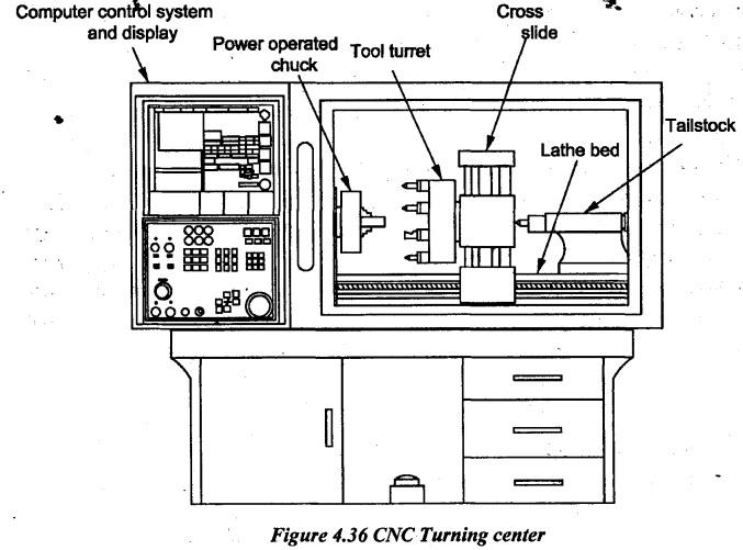
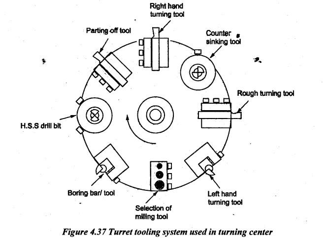
TURNING CENTERS We know that the turning operation reduces the diameter of a workpiece to a specified dimension and produces a smooth part finish. A turning center is a lathe with a Computer Numerical Control (CNC). Sophisticated turning centers can also perform a variety of milling and drilling operations. CNC lathe machines or CNC turning machines are machine tools which rotate a bar of material thereby allowing the cutting tool to remove material from the bar until the desired product is retained. The material itself is secured to and rotated by the main spindle while the cutting tool can be moved along multiple axis. Cylindrical or symmetrical parts around an axis are produced by a CNC lathe. Horizontal CNC turning machines are more commonly used but vertical machines use gravity. CNC turning centers are advanced computer numerically controlled machines. They have 3, 4, or even 5 axes along with a multitude of cutting capabilities, including facing, threading, knurling, milling, drilling, boring, reaming and taper turning drilling. Often the'se machines have an enclosed setup to ensure any cut material, coolant and components remain within the machine. Use of higher axes machines reduces cycle time by machining complex components using a single setup. In addition to time savings, (i) Improved accuracy can also be achieved as positioning errors between setups are eliminated. (ii) Improved surface finish and tool life by tilting the tool to maintain optimum tool to part contact all the times. (iii) Improved access to under cuts and deep pockets. By tilting the tool, the tool can be made perpendicular to the work surface and the errors are reduced as the major component of cutting force will be along the tool axis. (iv) Higher axes machining is widely used for machining sculptures surfaces in aerospace and automobile industry. The CNC lathe is a simpler 2-axis (X and Z-axis) machine that is computer-controlled and generally has one spindle. They are commonly flat-bed type and may have only minimal protective enclosure around the machine and the machine ways. CNC turning centers are also computer controlled but are more powerful and can have 3, 4 or 5-axes with more versatile capabilities and applications such as turning, drilling, tapping, and milling using live tools with powered rotary tool turret, sub-spindle (dual spindles), Y-axis, and multiple turrets. They are usually slant-bed type and have full machine enclosures to keep chips and coolant splashes within the machine. CNC turning centers have higher production capabilities than CNC lathes. 1. Construction and Working of Turning Centre A CNC Turning Centre is a complex machine which performs both turning and milling processes. It is a computer controlled turning centre in which designs are started on CAD software and exported as CAM files. These files are used to drive the motors of the turret tool post, chuck and machine bed in such a way to allow the manufacturing complexity as well as precision engineering. Figure 4.36 shows the constructional features of a CNC turning center. The basic parts of turning center are similar to conventional lathe as follows: (i) Bed (ii) Headstock (iii) Tailstock (iv) Carriage (v) Turret (vi) Cross slide etc. In addition, turning centers have CNC system which includes program input and display devices, machine control unit, drive systems and automated tooling system. The detailed constructional features of these devices can be found in Chapters 4.3.4, 4.3.5, 4.3.7, 4.3.8, 4.3.9, 4.7 and 4.8. (i) Bed: Bed is the base of machines. It is made of cast iron on which various fixed and operational parts are mounted. It carries a headstock on its left end and tailstock on its right end. Also, it spans the distance from the headstock to the tailstock. It is positioned under the workspace. Tool turret and various attachments move along the rails or ways of the bed across the length. The bed is very strong to resist the cutting forces and vibrations. It is rigidly held by cross ribs supported by cast iron supports. Linear guideways are better suited for higher rapids traverse and machining of abrasive materials. Solid box ways are suited for heavier or interruptive cuts with better tool rigidity. It should sufficiently be rigid to prevent the deflection under high cutting pressure transmitted through the tool post and carriage. There is a rack under the front way of the bed. A pinion gear is meshed with rack for moving the carriage when the hand wheel is turned. (ii) Headstock: The headstock assembly is permanently fastened to the left end of the bed. It carries a hollow spindle so that bars can be passed through it when it is required. The nose of the spindle is threaded to hold the chuck or faceplate. The spindle is rotated by a combination of gears and cone pulleys or by gears alone. The spindle has a taper at the front end for holding centres and other tools have a tapered shank. The spindle bore or bar capacity determines the maximum diameter of a workpiece that can be mounted thru the head stock. A live centre can be attached to the spindle. This centre is called live centre because it turns with the work. One of the main features of this headstock is the provision for rapid stopping, starting and speed changing. It helps in the rapid selection of required cutting speed and at the same time to minimize the loss of time in speed changing, stopping and starting. The headstock may be of four main types as follows. (i) Back geared or Step cone pulley driven headstock (ii) Direct electric motor driven headstock (iii) All geared headstock (iv) Pre-selective stock. There are speed changing and feed changing levers attached to the headstock. For detailed explanation of headstock mechanism, refer chapter 2.19.1 on Page 2.67. (iii) Tailstock: The tailstock is mounted on the right side of the lathe bed and slides along it in alignment with the headstock Z-axis. The primary function of the tailstock is to provide support to the workpiece being machined between centers. The tailstock has a quill with a taper to hold tooling. CNC turning centers with sub-spindles (or dual spindles) have a second spindle instead of a tailstock. The sub-spindle can move in the Z-axis longitudinally towards the main spindle under CNC control. Sub-spindle enables the machining of the back-side of a workpiece without any extra operator loading/unloading in the work process. (iv) Carriage: The carriage supports the cutting tool turret, guided and feeds against the workpiece. The main parts consist of the saddle, cross-slide and turret. Turning centers with live tool turrets have powered rotary tools in milling operations to increase the capabilities of the machine and reduce the second operations on workpieces. (v) cross-slide: A cross-slide moves on the carriage and has a feed screw which travels perpendicular to the main spindle axis. It allows facing operations to be performed and the depth of cut to be adjusted. This feed screw can be engaged through a gear train to the feed shaft which incorporated with automated power feed movement to the cross-slide. In most of the lathes, only one direction can be engaged at a time as an interlock mechanism to shut out the second gear train. (vi) Turret: A CNC Turning Centre usually has a more complex tool post than a conventional lathe. It allows the CNC to be used for more complex work without manually changing lathe tools. A turret tool system is shown in Figure 4.37. A variety of tools are set up on a rotating turret to perform a variety of machining processes that can be carried out. For example, a straight turning tool is used for facing a piece of round section on mild steel component followed by drilling process. CNC machine is programmed to carry out the facing off first and the drilling is performed by rotating the turret. Figure 4.37 shows a typical arrangement of tools set up on a turret tooling system. So, the turret performs a combination of lathe and milling processes to take place one after the other without manual changing of tools. 2. Types of CNC Turning Centers Based on the construction, the CNC turning centers are classified as: (i) Horizontal turning centers (ii) Vertical turning centers Horizontal turning centers are the most common type. With a horizontal turning center, the spindle is horizontally oriented and tools are mounted out of the side of tool holder to machine across the workpiece. In this type of turning center the chips are pulled away from the workpiece by gravity. Vertical turning centers are called a vertical turret lathe in which spindle is mounted vertically and allowed the headstock to sit on the floor. But, the faceplate becomes a horizontal rotating table. It provides the special advantage of machining large, heavy and short workpieces. Also, gravity contributes to seat the workpiece into the work holding devices. However, chips coming out of the machining surfaces become a problem because gravity does not provide necessary support in chip evacuation from the workpiece. According to the variants of turning machines, CNC turning centers are two types. (i) Swiss type and (ii) Vertical Turning Lathes (VTL) type (i) Swiss Type: These turning centers are with smaller parts 1.25" and under. They are used for higher production rates, faster cycle times and fully automated operation. Usually, they slide the material through a rotating collet where multiple tools approach the material after performing a variety of operations. They are commonly used in the medical, contact and gas consumable industry Swiss type CNC Lathes are an important production machine. (ii) Vertical Turning Lathes (VTL) Type: Vertical turning lathes are not similar to a machine with a vertically suspended and moving chuck used to pick up, machine and place parts. These machines are larger and used for turning things such as valve housings, large gear rings etc. 3. Advantages of CNC Turning Center Machines (i) Higher productivity: Once the new feedstock can be easily loaded into the chuck from the spindle side automatically, these machines can run independently for many cycles. If equipped with the right automation, the production is continuous and it improves productivity especially for hours in mass production thereby minimizing operator intervention. (ii) Built in automation: With the CNC Controller driving all functions of the machine, tool changes, coolant use, chip removal and part collection are all automated features. (iii) Configuration: CNC turning center is equipped with live tools and tool magazine. Also, the tools on the turning center are easy to index to make the location of the tool relative to the workpiece to move fast and accurately. (iv) Versatility: CNC turning center does not perform only turning operation but also perform facing, drilling, boring and milling to create complex parts and features. The workpiece is held in a position of turning center, then a live tool does machining operation. (v) Workholding: The turning centers do not require fixtures and clamping devices for workholding as the parts can be fixed on the chuck located on the spindle. Therefore, it saves time for loading and unloading of clamps. (vi) Quality: CNC turning center can shorten the whole manufacturing process, simplify the complexity and achieve higher standards. It leads to good surface finish due to the constant contact between the workpiece and tool. (vii) Increased Accuracy: When verified parts come off a CNC Turning Center consistent and repeatable, this increased accuracy is an added advantage for ever tighter and tighter tolerances to be achieved. (vii) Reduced Waste: After CNC Turning Center is setup and producing parts, accurate and usable components can be counted thereby reducing scrap. (vii) Lower cost: Automating any process consequently reduces the part cost by drastically reducing the man hours required to produce it.Difference between CNC turning centers and CNC lathes:
Manufacturing Technology: Unit IV: CNC Machines : Tag: : CNC Machines - Manufacturing Technology - Turning Centers
Related Topics
Related Subjects

Manufacturing Technology
ME3493 4th semester Mechanical Dept | 2021 Regulation | 4th Semester Mechanical Dept 2021 Regulation