Engineering Graphics: Unit II (c): Projections of Straight Lines
Traces of a Line
Engineering Graphics (EG)
The point of intersection of line with a plane is called its trace.
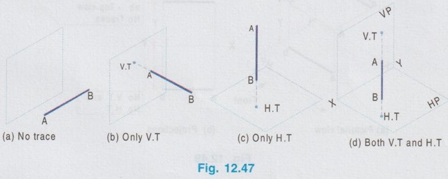
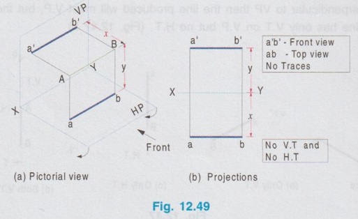
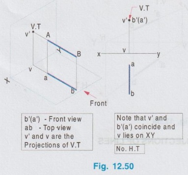
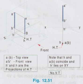
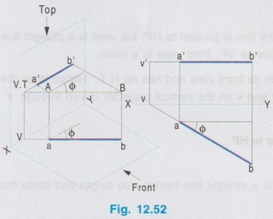
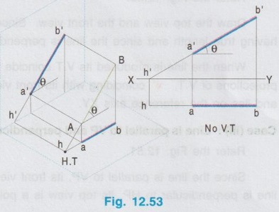
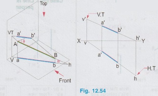
TRACES OF A LINE The point of intersection of line with a plane is called its trace. When a line is inclined or perpendicular to a reference plane and if it is produced it will meet that plane at a point. This point is known as the trace of the line. But when a line is parallel to any plane, if produced, it will not meet that plane and hence the parallel line has no trace on that plane. Traces are classified into two types according to the plane on which it occurs as (i) Horizontal trace and (ii) Vertical trace. (i) Horizontal Trace (H.T): The point of intersection of a line or line produced with HP is called Horizontal Trace. It is denoted as H.T [Fig. 12.46(b)] (ii) Vertical Trace (V.T) : The point of intersection of a line or line produced with VP is called vertical trace. It is denoted as V.T [Fig. 12.46(a)] It is to be noted that if a line is parallel to any plane, the line (or) line produced will not meet that plane. Hence it has no trace on that plane (Fig. 12.47 a). If a line is perpendicular to VP then the line produced will meet V.P, but the line is parallel to H.P. Hence the line has only V.T on V.P but no H.T (Fig. 12.47 b) Similarly if a line is perpendicular to HP then the line produced will meet H.P, but the line is parallel to VP. Hence the line has only H.T on HP but no V.T (Fig. 12.47 c). If a line is inclined to both the planes, the line produced will meet both the planes. Hence the line has both V.T and H.T (Fig. 12.47 d). Consider a line AB as shown in Fig. 12.48(a) which has got H.T on H.P. Now if the point H.T is viewed from top for its top view, top view coincides with H.T itself. Let it be h. Similarly when the point H.T is viewed from front for its front view its front view projection can be seen on the reference axis (since H.T lies on H.P). Let it be h'. Hence h and h' are the top view and front view of H.T respectively. Consider a line AB as shown in Fig. 12.48 (b) which has got V.T on V.P. Look at the point V.T from top and front for its top view and front view respectively. The top view projection lies on reference axis since the point V.T lies on V.P. Let it be v. The front view projection is the point V.T itself, let it be v'. Hence v and v' are the top view and front view of V.T respectively. Horizontal and vertical traces and their projections (Front view and Top view) can be drawn for a line for various positions of the line with respect to H.P and V.P as below : Case (1) Line is parallel to both HP & VP Case (II): Line is parallel to HP and perpendicular to VP Case (III): Line is parallel to VP and perpendicular to HP Case (IV): Line is parallel to HP and inclined to VP Case (V): Line is parallel to VP and inclined to HP Case (VI): Line is inclined to both HP and VP h' and h are the projections of H.T ; v' and v are the projections of V.T Note that h' and h are on the same projector, and v' and v are on the same projector. Also note that plan of V.T (ie v) and the elevation of H.T (ie, h') lies on the reference axis XY.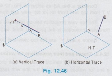
1. Top view and Front view of H.T (Fig. 12.48 a)
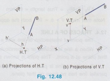
2. Top view and Front view of V.T (Fig. 12.48 b)
3. Traces and their projections for various positions of line
Engineering Graphics: Unit II (c): Projections of Straight Lines : Tag: : Engineering Graphics (EG) - Traces of a Line
Related Topics
Related Subjects

Engineering Graphics
GE3251 eg 2nd semester | 2021 Regulation | 2nd Semester Common to all Dept 2021 Regulation