Strength of Materials: Unit III: Torsion
Torsion and springs
Introduction, torsional rigidity
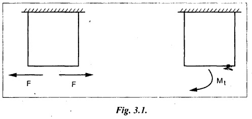
A pair of forces of equal magnitude but opposite in directions acting on a body is shown in Fig.3.1.
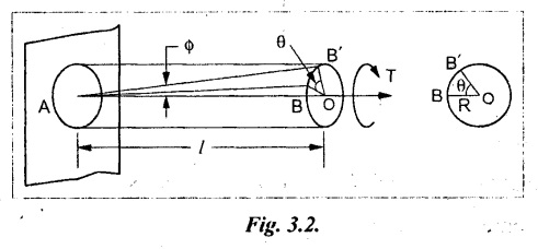
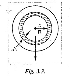
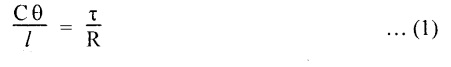
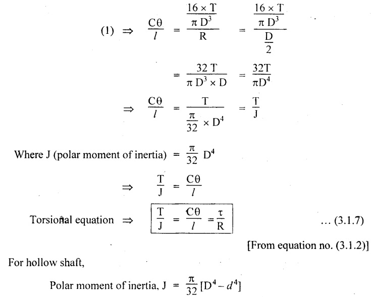
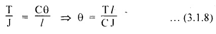
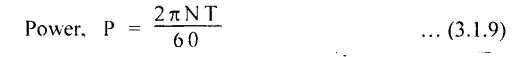
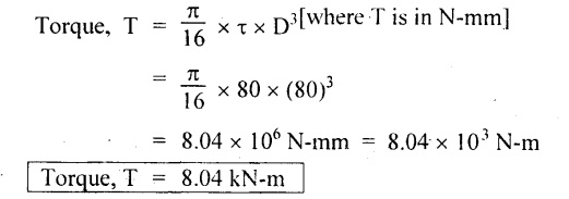
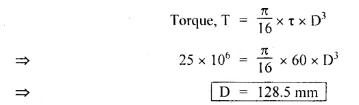
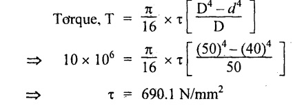
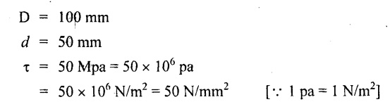
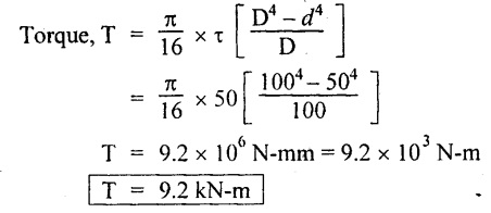
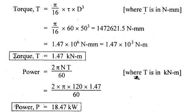
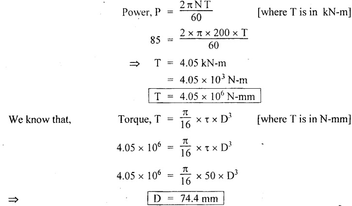
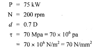
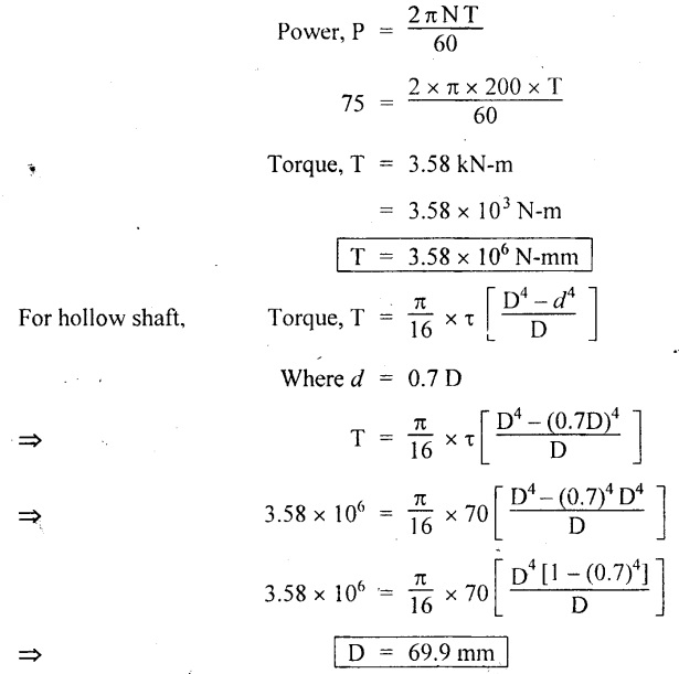
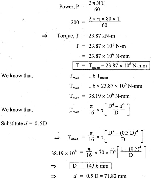
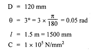
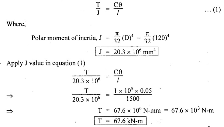
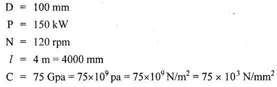
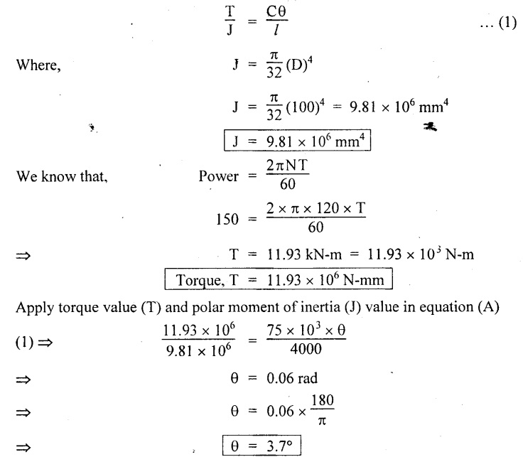
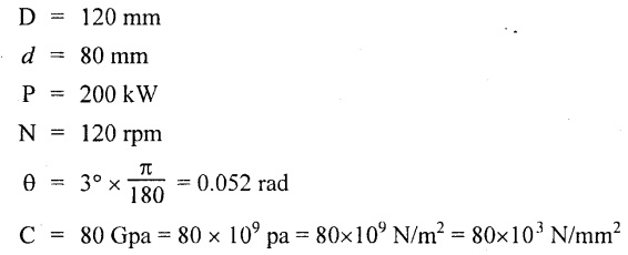
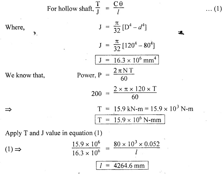
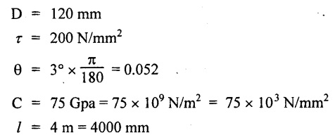
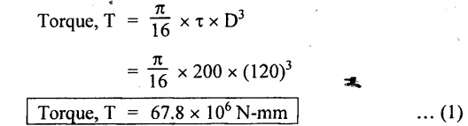
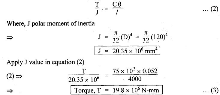
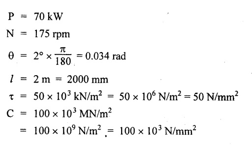
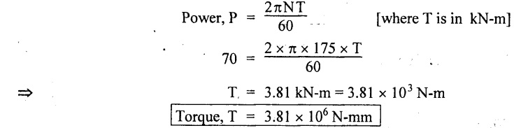
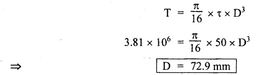
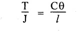
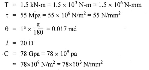
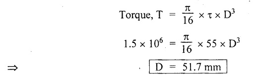
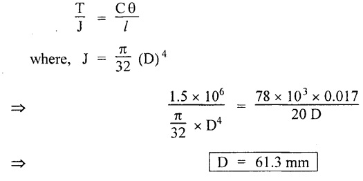
Chapter - 3: TORSION AND SPRINGS • Torsion of Circular and Hollow Shafts • Stresses and Deformation in Solid and Hollow Shafts • Stepped Shafts • Compound Shafts • Shafts in Series • Shafts in Parallel • Deflection of Shafts fixed at both ends • Strain energy due to torsion • Modulus of Rupture • Types of Springs • Springs in Series and Parallel • Deflection of Springs • Leaf Spring TORSION A pair of forces of equal magnitude but opposite in directions acting on a body is shown in Fig.3.1. These forces form a couple that tends to twist the body. Such a couple is known as twisting moment or torsional moment or simply as torque. Torque is equal to the product of the force applied, and the distance between the point of application of the force and the axis of the shaft. 1. The material of the shaft is homogeneous, perfectly elastic and obeys Hooke's law. 2. Twist is uniform along the length of the shaft. 3. The stress does not exceed the limit of proportionality. 4. The shaft circular in section remains circular after loading. 5. Strain and deformations are small. Consider a shaft of length l, radius R fixed at one end and subjected to a torque T at the other end is shown in Fig.3.2. Let 'O' be the centre of circular section, 'B' a point on surface and AB be the line on the shaft parallel to the axis of the shaft. When the shaft is subjected to torque 'T', B is moved to B'. If 'o' is shear strain and '0' is the angle of twist in length l, then If 'τ' is the shear stress and 'C' is the modulus of rigidity then Substitute ϕ value in equation (3.1.1) Consider a solid shaft of radius R and shear stress τx. Let us consider small elemental area of thickness 'dx'. Turning force on the shaft = τx ̧× 2 πx × dx Turning moment on the shaft dT = τx × 2 πx × dx × x Total turning moment can be obtained by Substitute τx value in equation (3.1.3) Consider a hollow circular shaft of outer radius R, inner radius r, and shear stress τx. Let us consider a small elemental area of thickness dx. The turning force on the hollow shaft = τx × 2 πx × dx Turning moment, dT = τx × 2 πx × dx × x Total turning moment can be obtained by Substitute τx value in equation (3.1.5), From equation (3.1.2), we know that Where, C - Modulus of rigidity - N/mm2 θ - Angle of twist - rad l - Length - mm τ - Shear stress - N/mm2 R - Radius - mm We know that, Substitute τ value in equation (1) D - Outer diameter d → Inner diameter From the torsional equation, we know that Since C, l and J are constant for a given shaft, 0 (angle of twist) is directly proportional to T (Torque). The term CJ is known as torsional rigidity and it is represented by K. Consider a rotating shaft which transmits power from one of its ends to another. Where, N = Number of revolution per minute T = Torque in KN-m P = Power in kW 1. Considering shear stress For solid shaft: Where, Torque, T in N-mm Shear stress, τ in N/mm2 Diameter, D in mm For hollow shaft: Where, Torque, T in N-mm Shear stress, τ in N/mm2 Diameter, D in mm External Diameter, D in mm Internal diameter, d in mm 2. Considering angle of twist For solid shaft: Where, Torque. T in N-mm Polar moment of inertia (J) = Modulus of rigidity C or G in N/mm4 Angle of twist. 0 in rad Length. l in mm For hollow shaft: Where, D - External diameter in mm d - Internal diameter in mm 3. Power Where, Power, P in kW Speed, N in rpm Torque, T in kN-m 4. % of saving in weight Where, D - Diameter of the shaft in mm ρ - Density of the shaft in kg/mm3 L - Length of the shaft in mm Weight of hollow shaft = Area × ρ × L 5. % of saving in material Example 3.1 : A circular shaft of 80 mm diameter is required to transmit torque Find the safe torque if the shear stress is not to exceed 80 Mpa. Given data: D = 80 mm τ = 80 Mpa = 80 × 106 pa = 80 × 106 N/m2 = 80 N/mm2 To find: Torque, T Solution: For solid shaft (considering shear stress) Result: Torque, T = 8.04 kN-m Example 3.2 A solid shaft is to transmit a torque of 25 kN-m. If the shearing stress is not to exceed 60 Mpa, Find the minimum diameter of the shaft. Given data: T = 25 kN-m = 25 × 103 N-m = 25 × 106 N-mm τ = 60 Mpa = 60 × 106 pa = 60 × 106 N/m2 = 60 N/mm2 [⸪ 1 pa = 1 N/m2] To find: Diameter of the shaft Solution: For solid shaft (considering shear stress) Result: Diameter of the shaft, D = 128.5 mm Example 3.3 A hollow circular shaft of external diameter 50 mm and internal diameter 40 mm transmits a torque of 10 kN-m. Find the maximum shear stress induced in the shaft. Given data: D = 50 mm d = 40 mm T = 10 kN-m = 10 × 103 N-m 10 × 106 N-mm To find: Shear stress (τ) Solution: For hollow shaft, Result: Shear stress, τ = 690.1 N/mm2 Example 3.4 A hollow shaft of external diameter 100 mm and internal diameter 50 mm is required to transmit torque from one end to the other. Find the safe torque which the shaft can transmit, if the shear stress is not to exceed 50 Mpa. Given data: To find: Torque (T) Solution: For hollow shaft, Result: Torque, T = 9.2 kN-m Example 3.5 Find the power that can be transmitted by a shafi of 50 mm diameter at a speed of 120 rpm, if the shear stress is 60 N/mm2. Given data: D = 50 mm N = 120 rpm Τ = 60 N/mm2 To find: Power Solution: For solid shaft. (considering shear stress) Result: Power. P = 18.47 kW Example 3.6 A solid steel shaft has to transmit 100 kW at 150 rpm. Find the shear stress if diameter is 75 mm. Given data: P = 100 kW N = 150 rpm D = 75 mm To find: Shear scess (τ) Solution: Power transmitted by the shaft is given by Shear stress, τ = 76.7 N/mm2 Example 3.7 A solid circular shaft transmits 85 kW power at 200 rpm. Calculate the shaft diameter if the shear stress is 50 MN/m2. Given data: P = 85 kW N = 200 rpm To find: Shaft diameter (D) Solution: We know that, Result: Shaft diameter, D = 74.4 mm Example 3.8 A hollow steel shaft is to transmit 75 kW at 200 rpm. Find the outer diameter of the shaft where inside diameter is 0.7 of the outside. Taking allowable shear stress as 70 Mpa. Given data: To find: Outer diameter, D Solution: We know that, Result: outer diameter of the shaft , D = 69.9 mm. Example 3.9 A hollow shaft is to transmit 200 kW at 80 rpm. If the shear stress is not to exceed 70 MN/m2 and internal diameter is 0.5 of the external diameter. Find the external and internal diameters assuming that maximum torque is 1.6 times the mean. Given data: To find: External diameter (D) Internal diameter (d) Solution: We know that, Result: Outer diameter, D = 143.6 mm Inner diameter, d = 71.82 mm Example 3.10 Find the maximum torque that can be safely applied to a shaft of 120 mm diameter. If the allowable twist is 3° in a length of 1.5 m. Take Given data: To find: Torque (T) Solution: For solid shaft, (considering angle of twist) Result: Torque, T = 67.6 KN-m Example 3.11 A solid shaft of diameter 100 mm is required to transmit 150 kW at 120 rpm. If the length of the shaft is 4m and modulus of rigidity for the shaft is 75 Gpa, find the angle of twist. Given data: To find: Angle of twist Solution: For solid shaft, (considering angle of twist) Result: Angle of twist, θ = 3.7° Example 3.12 A hollow shaft of 120 mm external diameter and 80 mm internal diameter is required to transmit 200 kW at 120 rpm. If the angle of twist is not to exceed 3o, find length of the shaft. Take C = 80 Gpa. Given data: To find: Length of the shaft (l) Solution: For hollow shaft, (considering angle of twist) Result: Length of the shaft, l = 4264.6 mm Example 3.13 Find the maximum torque that can be safely applied to a shaft of 120 mm diameter. The permissible shear stress and allowable twist are 200 N/mm2 and 3° respectively. Take C 75 Gpa and length of shaft = 4 m. Given data: To find: Maximum torque, (Tmax) Solution: Shear stress and angle of twist both are given. First case: Considering shear stress Second case: Considering angle of twist From equations (1) and (3) we find that the maximum torque that can be safely applied on the shaft is 19.8 × 10⁶ N-mm (i.e., Smaller of the two values). Result: Maximum torque, T = 19.8 × 10⁶ N-mm Example 3.14 A solid circular shaft transmits 70 kW power at 175 rpm. Calculate the shaft diameter, if the twist in the shaft is not to exceed 2° in 2 meter length of shaft and shear stress is limited to 50 × 103 kN/m2. Take C = 100 × 103 MN/m2. Given data: To find: Diameter of the shaft Solution: We know that, Shear stress and angle of twist both are given: First case: Considering shear stress (τ) Second case: Considering angle of twist Where, J polar moment of inertia From the above two cases, we find that suitable diameter for the shaft is 72.9 mm (i.e., greater of the two values). Result: Shaft diameter, D = 72.9 ≈ 73 mm Example 3.15 A solid shaft is subjected to a torque of 1.5 kN-m. Find the necessary diameter of the shaft, if the allowable shear stress is 55 Mpa. The allowable twist is 1°for every 20 diameters length of the shaft. Take C = 78 Gpa. Given data: To find: Diameter of the shaft Solution: Shear stress and angle of twist both are given. First case: Considering shear stress (τ) Second case: Considering angle of twist (θ)
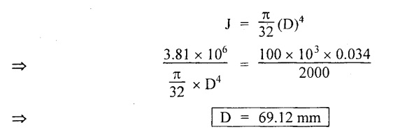
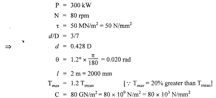
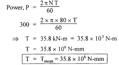
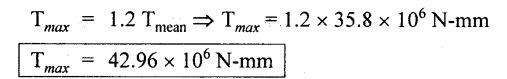
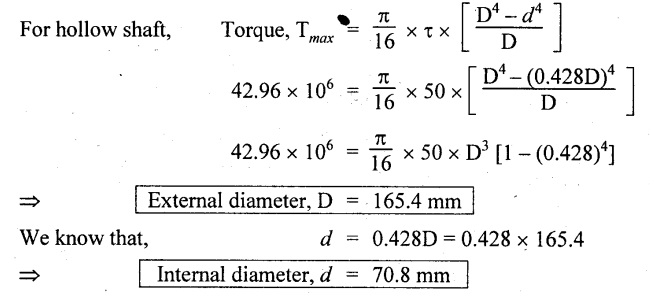
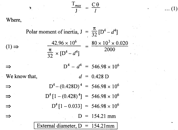
From the above two cases, we find that suitable diameter for the shaft is 61.3 mm (i.e., greater of the two values). Result: Shaft diameter, D = 61.3 mm Example 3.16 A hollow shaft is to transmit 300 kW at 80 rpm. If the shear stress is not to exceed 50 MN/m2 and diameter ratio is 3/7. Find the external and internal diameter if the twist is 1.2° and length is 2 m. Assuming maximum torque is 20% greater than mean. Take C-80 GN/m2. Given data: To find: External and internal diameters Solution: We know that, We know that, Shear stress and angle of twist both are given. First case: Considering shear stress (τ) Second case: Considering angle of twist (0) We know that, d = 0.428 D = 0.428 × 154.21 From the above two cases, we find that suitable external and internal diameter of the shaft is External diameter, D = 165.4 mm Internal diameter, d = 70.8 mm. (i.e., greater of the two values) Result: External diameter, D = 165.4 mm 1. INTRODUCTION
2. ASSUMPTIONS IN THE THEORY OF PURE TORSION
3. DERIVATION OF SHEAR STRESS PRODUCED IN A CIRCULAR SHAFT SUBJECTED TO TORSION


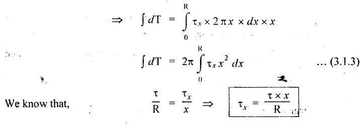
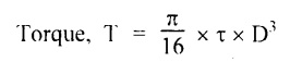
4. STRENGTH OF SOLID SHAFT OR MAXIMUM TORQUE TRANSMITTED BY A CIRCULAR SOLID BAR

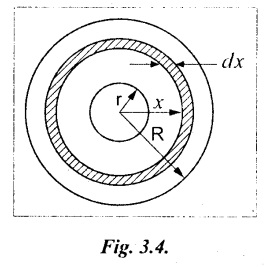
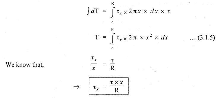
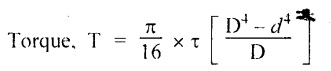
5. STRENGTH OF HOLLOW SHAFT OR MAXIMUM TORQUE TRANSMITTED BY A HOLLOW CIRCULAR BAR
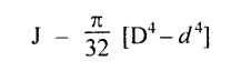
6. POLAR MOMENT OF INERTIA (J)

 Where,
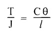
7. TORSIONAL RIGIDITY
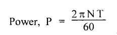
8. POWER TRANSMITTED BY THE SHAFT
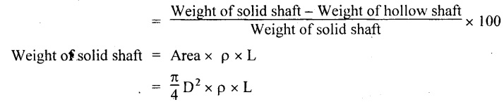
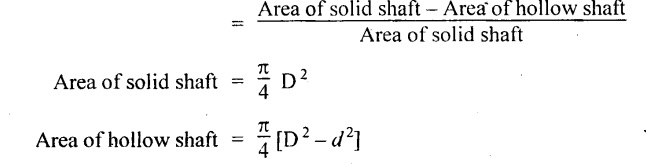
9. FORMULAE USED
![]() D4 in mm4
D4 in mm4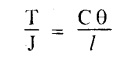

10. SOLVED PROBLEMS
 Result:
 ᎠᏎ -- ᏧᏎ
Strength of Materials: Unit III: Torsion : Tag: : Introduction, torsional rigidity - Torsion and springs
Related Topics
Related Subjects
Strength of Materials
CE3491 4th semester Mechanical Dept | 2021 Regulation | 4th Semester Mechanical Dept 2021 Regulation