Theory of Machines: Unit II: Gears and Gear Trains
Torques and tooth loads in epicyclic gear trains
Gears and Gear Trains - Theory of Machines
Assuming that all gears of the epicyclic gear train rotates at uniform speeds, their angular accelerations are zero. Therefore the inertia torques of the epicyclic gear trains are zero.
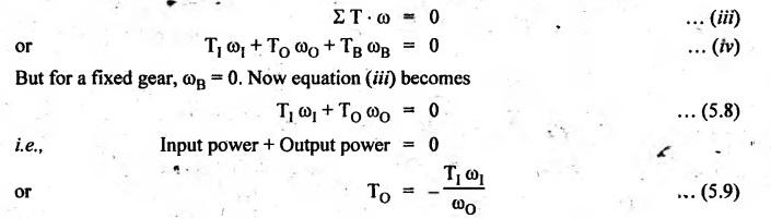
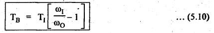
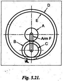
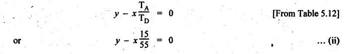
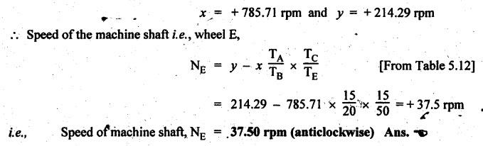
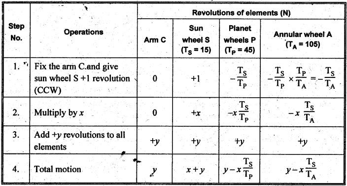
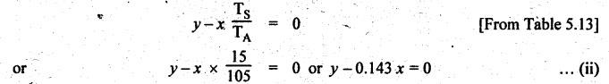
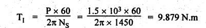
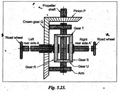
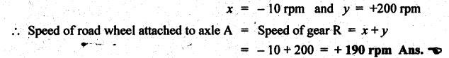
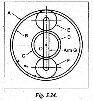
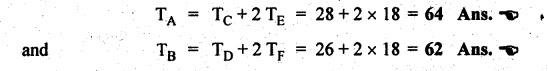
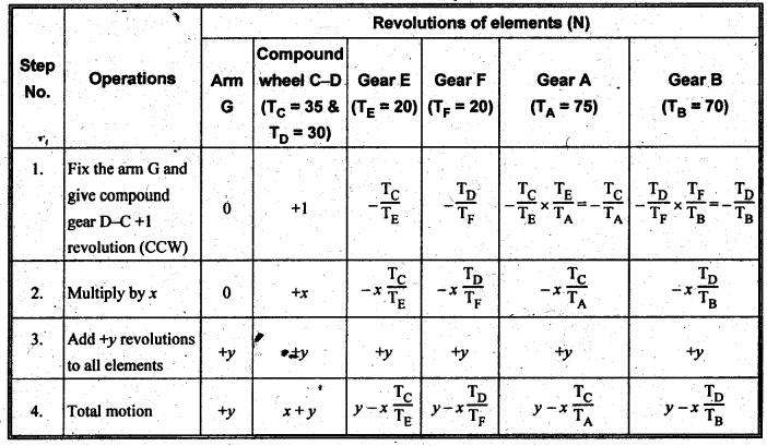
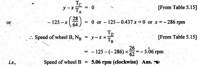
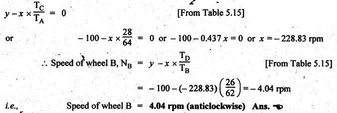
TORQUES AND TOOTH LOADS IN EPICYCLIC GEAR TRAINS Let T1 = Input torque on the driving member, TO = Output or resisting or load torque on the driven member, and TB = Holding or braking or fixing torque on the fixed gear. Assuming that all gears of the epicyclic gear train rotates at uniform speeds, their angular accelerations are zero. Therefore the inertia torques of the epicyclic gear trains are zero. Since inertia torques are neglected, therefore the algebraic sum of all the external torques is zero for the equilibrium of gear train. That is, where F1, FD and FB are the tooth loads at radii r1, rO and rB respectively on driving, driven and fixed gears. If there are no frictional losses within the gear train (i.e., the system operates at 100% efficiency), then the energy balance indicates Substituting the value TO in equation (i), we get The equation (5.10) will be useful for calculating the braking or fixing torque required to be applied to the fixed gear. The equation (5.7) can be used to determine the tooth loads. Note The efficiency of the gear train is given by Example 5.15 An epicyclic gear train is shown in Fig.5.21. Pinion A has 15 teeth and is rigidly fixed in the motor shaft. The wheel B has 20 teeth and gears with A, and also with annular fixed wheel D. Pinion C has 15 teeth and is integral with B (C, B being a compound gear wheel). Gear C meshes with annular wheel E, which is keyed to the machine shaft. The arm rotates about the same shaft on which A is fixed and carries the compound wheel B-C. If the motor runs at 1000 rpm, find the speed of the machine shaft. Find the torque exerted on the machine shaft if motor develops a torque of 100 N.m. [A.U., Nov/Dec 2009] Given data: TA = 15; TB = 20; TC = 15; NA = 1000 rpm; TA = 100 N.m Solution: The gear arrangement is shown in Fig.5.21. From the geometry of Fig.5.21, we can write. dD = dA + 2dB and dE = dD - dB + dC where dA, dB, dC, dD and dE are the pitch circle diameters of the gear wheels A, B, C, D and E respectively. We know that for the same module, the number of teeth are proportional to the pitch circle diameters. Therefore TD = TA + 2 TB = 15 + 2 × 20 = 55 and TE = TD - TB + TC = 55 – 20 + 15 = 50 Speed of the machine shaft: The motion of various elements is shown in Table 5.12. Table 5.12. Motion of elements Given conditions are: (i) Pinion A rotates at 1000 rpm, so (ii) The annular wheel D is fixed, so Solving equations (i) and (ii), we get Torque exerted on the machine shaft: We know that, Input power + Output power = 0 Example 5.16 An epicyclic gear train for an electric motor is shown in Fig.5.22. The wheel S has 15 teeth and is fixed to motor shaft rotating at 1450 rpm: The planet P has 45 teeth, gears with fixed annular A and rotates on a spindle carried by an arm which is fixed to output shaft. The planet P also gears with the sun wheel S. Find the speed of output shaft. If motor is transmitting 1.5 kW, find the torque required to fix the annular. Given data: TS = 15; NS = 1450 rpm; TP = 45; P = 1.5 Kw = 1.5 × 10³ W Solution: The gear arrangement is shown in Fig.5.22. From the geometry of Fig.5.22, we can write dA = dS + 2 dP where dA, dS and dP are the pitch circle diameters of the gear wheels A, S and P respectively. We know that for the same module, the number of teeth are proportional to pitch circle diameters. Therefore TA = TS + 2 TP or TA = 15 + 2 (45) = 105 Speed of output shaft: The motion of various elements is shown in Table 5.13. Table 5.13. Motion of elements Given conditions are: (i) Motor shaft i.e., sun wheel S rotates at 1450 rpm, so (ii) Annular wheel A is fixed, so On solving equations (i) and (ii), we get Torque required to fix the annular wheel A: Input torque i.e., torque on sun wheel, S Since the efficiency is 100% throughout, therefore Input power + Output power = 0 Example 5.17 Fig.5.23 shows a differential gear used in a motion car. The pinion P on the propeller shaft has 12 teeth and gears with the crown gear Q which has 60 teeth. The shafts A and A'from the rear axles to which the road wheels are attached. If the propeller shaft rotates at 1000 rpm and the road wheel attached to axle Aʼhas a speed of 210 rpm, while taking a turn, find the speed of road wheel attached to axle A. Given data: TP = 12; TQ = 60; NP = 1000 rpm; NA = NS = 210 rpm Solution: The differential epicyclic gear train is shown in Fig.5.23. A note on differential gear of an automobile: • The function of a differential gear of an automobile is to: (i) transmit motion from engine to rear wheels, and (ii) rotate the rear wheels at different speeds while the automobile is taking a turn. • Necessity of differential gear in an automobile: When an automobile is running on a straight path, the speed of both the front and rear wheels is same. But when the automobile is taking a turn, left or right, the outer wheel will run faster than the inner wheel because at that time the outer rear wheel has to cover more distance than the inner rear wheel. This is accomplished by epicyclic bevel differential gear train, as shown in Fig.5.23:) We know that velocity ratio for pinion and crown gear meshing, The motion of various elements is shown in Table 5.14. Table 5.14. Motion of elements Given conditions are: (i) Gear Q rotates at 200 rpm, so (ii) Road wheel attached to axle A' i.e., the gear D rotates at 210 rpm, so Solving equations (i) and (ii), we get Example 5.18 In an epicyclic gear train, the internal wheels A and B and compound wheels C and D rotate independently about axis O. The wheels E and F rotate on pins fixed to the arm G. E gears with A and C. Wheel F gears with B and D. All the wheels have the same module and the number of the teeth are: TC = 28; TD = 26; TE = TF = 18. 1. Sketch the arrangement. 2. Find the number of teeth on A and B. 3. If the arm G makes 100 rpm clockwise and A is fixed, find the speed of B. 4. If the arm G makes 100 rpm clockwise and wheel A makes 10 rpm anticlockwise; find the speed of wheel B. Given data: TC = 28; TD = 26; TE = TF = 18 Solution: 1. Sketch the arrangement: The arrangement of the given gear is shown in Fig.5.24. 2. Number of teeth on wheels A and B: From the geometry of Fig.5.24, we can write dA = dC + 2 dE and dB = dD + 2 dF where dA, dB, dC, dD, dE and dF are the pitch circle diameter of wheels A, B, C, D, E and F respectively. We know that for the same module, the number of teeth are proportional to the pitch circle diameters. Therefore 3. Speed of wheel B when arm G makes 100 rpm clockwise and wheel A is fixed: The motion of various elements is shown in Table 5.15.- Table 5.15. Motion of elements Given conditions are: (i) Arm G makes 125 rpm clockwise, so y = -125 rpm (ii) Wheel A is fixed, so 4. Speed of wheel B when arm G makes 100 rpm clockwise and wheel A makes 10 rpm counter clockwise: The given conditions are: (i) Arm G makes 100 rpm clockwise, so y = -100 rpm (ii) Wheel A makes 10 rpm anticlockwise, so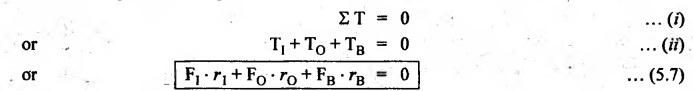


Theory of Machines: Unit II: Gears and Gear Trains : Tag: : Gears and Gear Trains - Theory of Machines - Torques and tooth loads in epicyclic gear trains
Related Topics
Related Subjects

Theory of Machines
ME3491 4th semester Mechanical Dept | 2021 Regulation | 4th Semester Mechanical Dept 2021 Regulation