Manufacturing Technology: Unit I: Mechanics of Metal Cutting
Tool nomenclature
Parts of a Single Point Cutting Tool, Angles
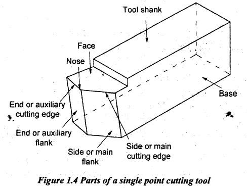
Naming the various angles and parts is known as nomenclature. The nomenclature of a single point cutting tool are shown in Figure 1.4.
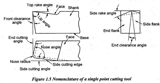
TOOL NOMENCLATURE Naming the various angles and parts is known as nomenclature. The nomenclature of a single point cutting tool are shown in Figure 1.4. (i) Shank: The body of the tool which is not ground is called shank. (ii) Face: The surface over which the chip of the metal slides is known as face. (iii) Flank: The surface of the tool which is facing the workpiece is known as flank. In single point cutting tools, generally, there are two flanks namely end or auxiliary flank and side or main flank. (iv) Base: It is the bottom surface of the shank. Generally, it is flat in nature. (v) Nose: The junction of sides and end cutting edges are called nose. (vi) Cutting edge: It is the junction of face and flank. It is generally denoted by two types of cutting edges. 1. End or auxiliary cutting edge 2. Side or main cutting edge The various angles of a single point cutting tool are shown in Figure 1.5. (1) Back Fake angle or top rake angle: It is the angle between the face of the tool and the line parallel to the base of the tool. It is the slope given to the face or surface of the tool. This slope is given from the nose along the length of the tool as shown in Figure 1.5. This angle may be positive or negative depending on the amount of side cutting edge. (i) Side rake angle: It is the slope given to the face or top of the tool. It is the angle between tool face and line parallel to the base of the tool as shown in Figure 1.5. This slope is given from the nose along the length of the tool. When the angle is positive, the slope is given towards the cutting edge and when the angle is negative, the slope is given away from the cutting edge. (iii) True rake: A combined front and side rake are provided on the tool suitably. The resultant slope is known as true rake. Generally, in all practical applications, the rake given on the tool face may be positive, zero or negative rake. (iv) Relief angle or clearance angle: It is the slope given downwards from cutting edges. There are two clearance angles as follows: (a) Front clearance or Side clearance angle or Side relief angle (b) End clearance angle or End relief angle. The angle between side flank and a line perpendicular to the base of the tool is known as side relief angle. The purpose of providing this angle is to avoid rubbing action when the tool is fed sideway into the job. If the side relief angle is larger, the cutting edge of the tool will break because of insufficient support whereas the side relief angle is very small. The tool cannot be fed into the job but it will rub against the job. So, the tool will be overheated. It will affect the surface finish of the job. The angle between end flank and a line perpendicular to the base of the tool measured at right angle to the end flank is known as end relief angle. This angle prevents the cutting tool- from rubbing against the job. If the angle is very larger, it will break due to insufficient support whereas if it is very small, the tool will rub against the job. Due to this, the cutting will not be proper and hence, the poor surface finish will be obtained. Generally, its value varies from 6° to 10°. (v) Cutting edge angles: There are two cutting edge angles namely side cutting edge angle and end cutting edge angle. Side cutting edge angle is the angle between side cutting edge and side of the tool shank. Otherwise, it is the angle between side cutting edge and longitudinal axis of the tool. It avoids the formation of built-up edge, controlling the flow of chip and distributing the cutting force. It has the following advantages. 1. It increases the tool life. 2. It reduces the chip thickness. 3. It allows the dissipation of heat quickly due to the wider cutting edge. 4. It improves the surface finish. End cutting edge angle is the angle between end cutting edge and a line perpendicular to the tool shank. Otherwise, it is the angle between the face of the tool and a plane perpendicular to the side of the shank. This angle will allow only small section of the end cutting edge to contact the machined surface and it prevents vibration and chatter. Normally, this angle varies from 5° to 15°. (vi) Nose radius: Nose is the junction of side cutting edge and end cutting edges. A slight curved profile is provided at this junction called nose radius. The line joining side and end cutting edges by a point leads to high heat concentration. Joining by means of a small radius is a good practice to increase the tool life and to ensure a better surface finish on the workpiece. Large radii strengthen the tool and hence, it is used on cast iron and castings where the cuts are interrupted. (vii) Lip angle: It is also called cutting angle. It is the angle between face and end surface of the tool.1. Parts of a Single Point Cutting Tool
2. Angles of Single Point Cutting Tool
Manufacturing Technology: Unit I: Mechanics of Metal Cutting : Tag: : Parts of a Single Point Cutting Tool, Angles - Tool nomenclature
Related Topics
Related Subjects

Manufacturing Technology
ME3493 4th semester Mechanical Dept | 2021 Regulation | 4th Semester Mechanical Dept 2021 Regulation