Manufacturing Technology: Unit I: Mechanics of Metal Cutting
Tool Life
Mechanics of Metal Cutting - Manufacturing Technology
Tool life is defined as the cutting time required for reaching a tool life criterion or time elapsed between two consecutive tool resharpening.
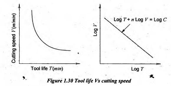
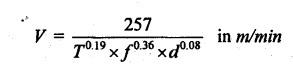
TOOL LIFE Tool life is defined as the cutting time required for reaching a tool life criterion or time elapsed between two consecutive tool resharpening. During this period, the tool serves effectively and efficiently. The tool life is an important factor in a cutting tool performance since a considerable time is lost whenever the tool is ground and reset. Therefore, the cutting tool should have a longer life. The following are some of ways of expressing tool life. (i) Volume of metal removed per grind. (ii) Number of workpieces machined per grind. (iii) Time unit. The life of the cutting tool is affected by the following factors. (i) Cutting speed (ii) Feed and depth of cut (iii) Tool geometry (iv) Tool material (v) Cutting fluid (vi) Work material (vii) Rigidity of work, tool and machine. 1. Cutting speed: Cutting speed has greater influence on the tool life. When the cutting speed increases, the cutting temperature will also increase. Due to this, the hardness of the tool decreases. Hence, the tool flank wears thereby leading to occurrence of crater wear. When the cutting speed increases, the tool life will decrease. The tool life will be increased at low cutting speeds. There is a definite relationship between cutting speed and tool life. This relation is given by Taylor's formula as follows: VTn = C where V = Cutting speed in m/min. T = Tool life in minutes. n = exponent or index which depends on the tool and work. = 0.1 to 0.5 for high speed steel tools = 0.2 to 0.4 for tungsten carbide tools = 0.4 to 0.6 for ceramic tools C = Constant. It is numerically equal to the cutting speed which gives a tool life of one minute. If the higher cutting speed is permitted by a tool for the same life, the tool is having better cutting properties and it will be more productive. For finding tool life, the tools are operated to failure at different cutting speeds and the test results are plotted. A typical cutting spéed (V) versus Tool life (T) relationship is shown in Figure 1.30. In general, a parabolic decrease in tool life with increased cutting speed is obtained. A relationship is plotted as a straight line on log – log graph as shown in Figure 1.30. These plots indicate that the cutting speed increases with the decrease in tool life. Obviously, if a very low cutting speed is used, the tool will lose its durability. If the surface finish of the tool is improved, both the tool life and efficiency of the tool are improved due to the friction between tool and chip is minimized. The roughness of the tools cutting edge could result in à concentration of stresses which may cause surface cracks and chipping of the tool. Generally, the following factors influenced the cutting speed permitted by a tool. • Tool life • Properties of material being machined • Rate of feed and depth of cut • Tool geometry • Cutting fluid used • Type of machining process • Surface finish to be obtained. 2. Feed and depth of cut: The life of the cutting tool is influenced by the amount of metal removed by the tool per minute. When the fine feed is used, the area of chip passing over the tool face is greater than a coarse feed for a given volume of metal removal. If the chip is thick, this advantage is offset. Besides, it is possible to balance two opposing influences to obtain optimum feed rate. The effect of feed and depth of cut on tool life is given by the formula where V - Cutting speed T - Tool life f - Feed in mm/min d - Depth of cut in mm This relation is generally applied for machining low carbon steel by a cemented carbide tool. Tool life is decreased with increase in feed and depth of cut. 3. Tool geometry: Large rake angle reduces the tool cross section. Hence, the amount of heat absorbed by the tool is also reduced. It weakens the tool. So, the correct rake angle must be used for long tool life. The optimum rake angle for maximum tool life lies between -5° to +10° for turning austenitic steel by a carbide tool. If the relief angle is more, less will be the friction of the tool on the work. But, more relief angle decreases the tool life because of decreased strength. The optimum relief angle is 12° to 15°. Similarly, a higher value of side cutting edge angle gives longer life to the tool. The optimum side cutting edge angle lies between 30° and 25°. The increase in nose radius improves the tool life since the stress concentration is less for greater nose radius. The relationship between cutting speed (V), tool life (T) and nose radius (r) is as follows VT0.0927 = 331 r0.244 The proper end cutting edge angle is provided to improve surface finish, rigidity and equivalent cutting speed. The optimum end cutting edge angle varies from 4° to 10°. 4. Tool material: An ideal tool material is one which removes the maximum volume of material at all cutting speed. Both physical and chemical properties of tool material will influence on tool life. For a given cutting speed, HSS tool is more durable than carbon steel tool. But carbide tools have more life than the high-speed tool. 5. Cutting fluid: Heat produced during metal cutting is carried away by tool and work by means of cutting fluid. It reduces the friction at chip-tool interface and it increases the tool life. The cutting fluid which directly controls the amount of heat at the chip-tool interface is given by the formula Tθn = C where T - Tool life θ - Temperature of chip tool interface in °C n - An index which depends on shape and material of the cutting tool. 6. Workpiece material: Tool life does also depend on the microstructure of the workpiece material. Tool life will be more when machining soft metals than hard metals such as cast iron and alloy steel. 7. Rigidity of work, tool and machine: A strongly supported tool on a rigid machine will have more life than tool machining under the vibrating machine. Loose workpiece will decrease the tool life. The volume of metal removal from the workpiece between tool sharpening for definite depth of cut, feed and cutting speed can be determined as follows. For example in case of turning, where Ꭰ - Diameter of workpiece (mm) N - R.P.M. of workpiece Let d - Depth of cut in mm f - Feed mm/min T - Time of tool failure in min L - Tool life in 1mm3 of metal removal Volume of metal removed per revolution = π Ddf mm3 Volume of metal removed per minute = π Ddf N mm3π Volume of metal removed in 'T" minute = Ddf N T mm3 ⸫ Volume of metal removed between tool grinds = л Ddf N T in mm3 L = л Ddf N T = 1000 V d f T in mm3 L = V d f T in cm31. Factors Affecting Tool Life
2. Tool Life Measurement in Terms of Metal Removal

Manufacturing Technology: Unit I: Mechanics of Metal Cutting : Tag: : Mechanics of Metal Cutting - Manufacturing Technology - Tool Life
Related Topics
Related Subjects

Manufacturing Technology
ME3493 4th semester Mechanical Dept | 2021 Regulation | 4th Semester Mechanical Dept 2021 Regulation