Manufacturing Technology: Unit II: Turning Machines
Tool layout
Turning Machines - Manufacturing Technology
Turret and capstan lathes are mainly used for machining workpieces at a rapid rate.
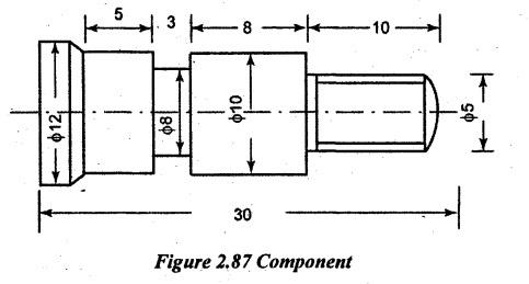
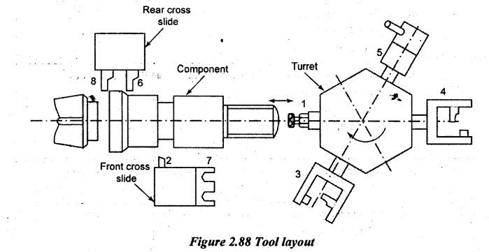
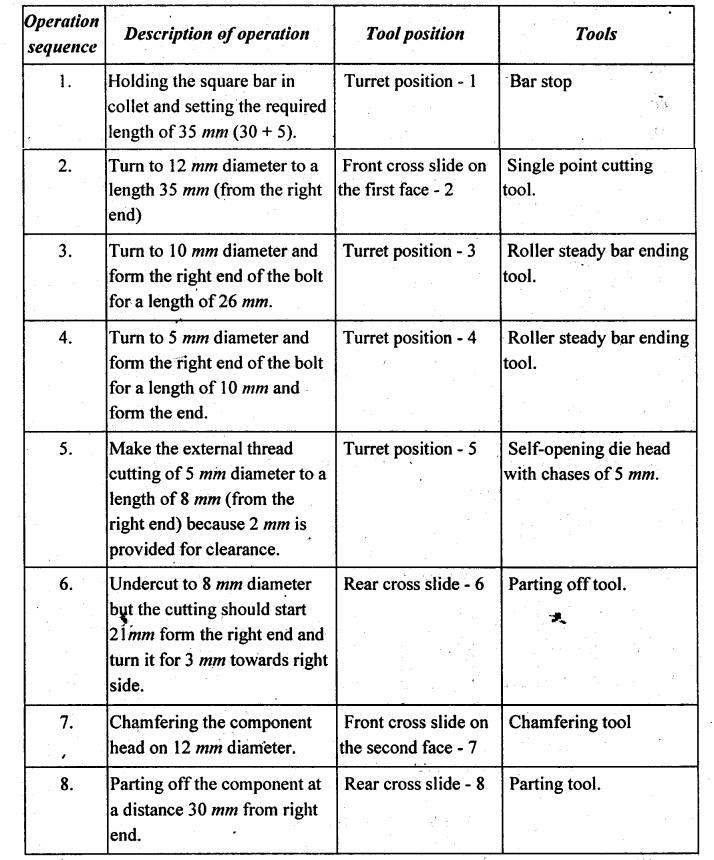
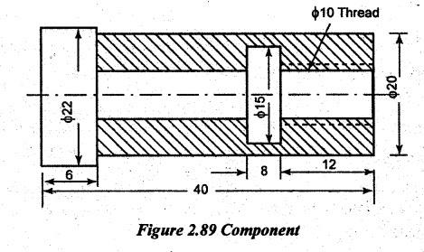
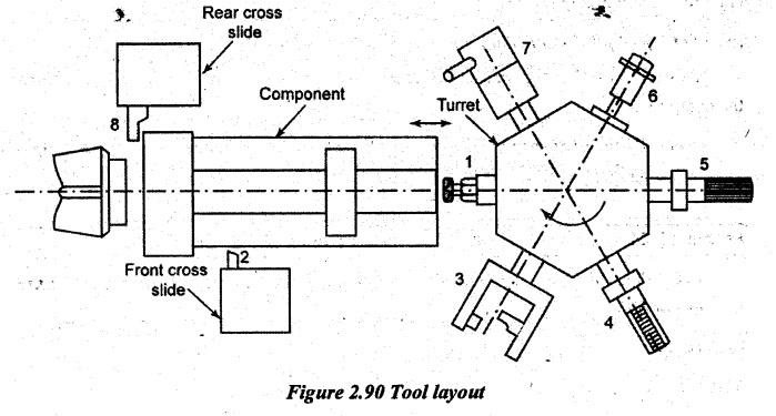
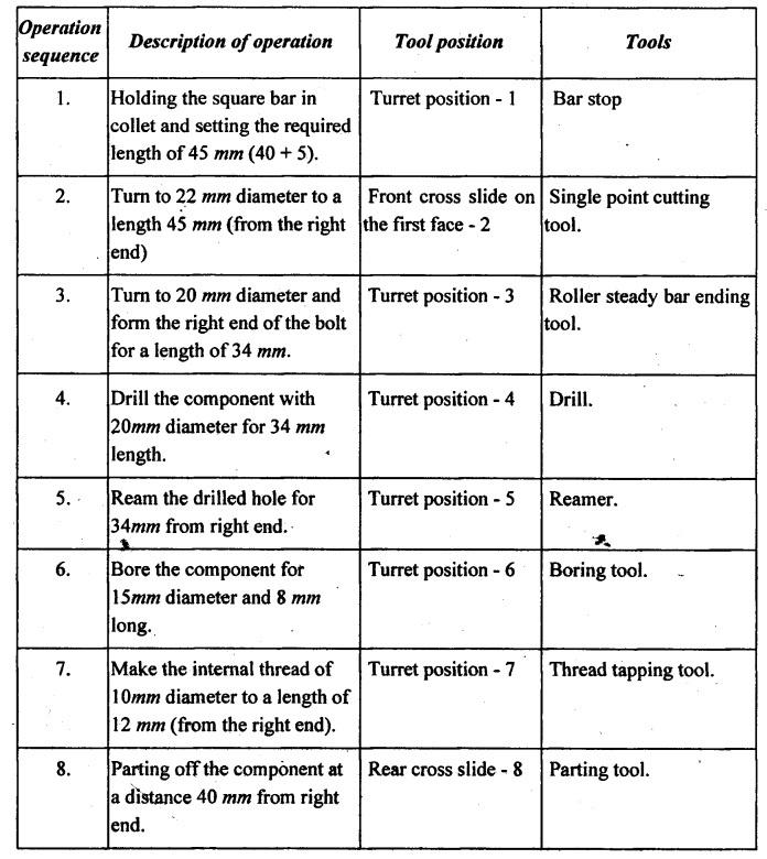
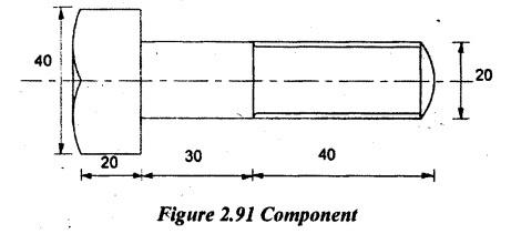
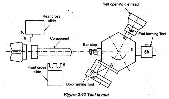
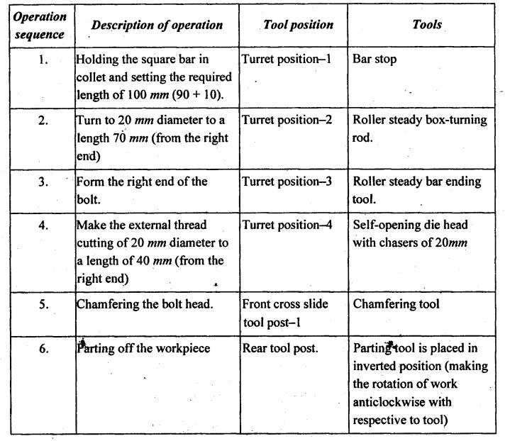
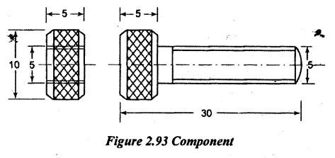
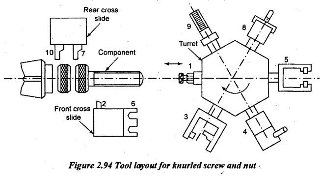
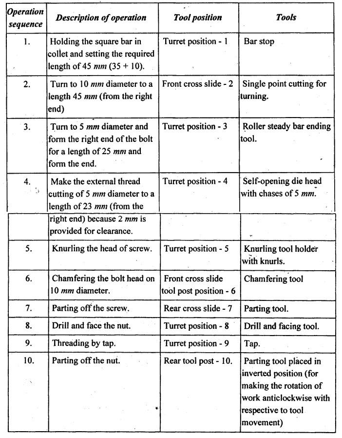
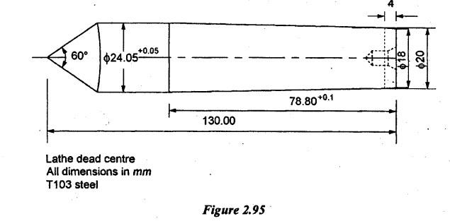
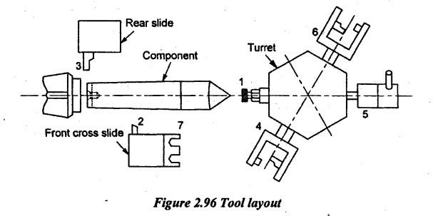
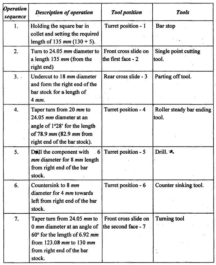
TOOL LAYOUT Turret and capstan lathes are mainly used for machining workpieces at a rapid rate. Before starting the production, the following works are carried out. 1. Selection of tools 2. Designing of special tools 3. Selection of speed 4. Selection of feed 5. Setting the required length of workpiece and tool travel length. These planning of operation sequence and preparation of turret or capstan are termed as tool layout. The accuracy and cost of the product are largely dependent on an efficient tool layout. The tool layout mainly consists of three stages. 1. Planning and scheduling stage: preparation of operation sheet with the order of operation. 2. Detailed sketching of various stages of machining operations in a sequence of operations. 3. Sketching the plan showing the various tools fitted into the hexagonal turret faces and on the cross slides in a proper sequence. The following rules should be kept in mind and followed in laying out the sequence of operations necessary to produce a workpiece on the turret lathe. 1. For small batch production, simple tool layout should be used with standard tools. For mass production, it will be more economical to use special tools to minimize the machining time. 2. Different machining operations should be done simultaneously as far as possible. 3. Similarly, the handling operations can also be combined with the machining operations such that the total machining time is reduced. 4. During simultaneous multiple cutting operations the cutting tools should be arranged in such a way that the cutting forces by various cutting tools get balanced. 5. The finishing cut should be done full length of the workpiece involving multiple rough cuts with different tools... 6. The contoured surface should be machined in two steps rather than single step to improve quality. 7. It is important to drill a centre hole before final drilling in the case of small diameter holes. 8. Large bores should start with drilling small holes and then extended using boring tools. 9. To drill long holes having length > 3 times the diameter, special care should be taken. Frequent withdrawal of the tool from the hole for flushing the chip from the drill flutes with cutting fluid is essential. 10. The operations involving heavy forces and it reduces rigidity of the workpiece such as deep grooves or large bores should not be carried out in early stages. 11. In the case of stepped holes, large diameter hole should be drilled first and then the smaller hole should be drilled. 1. The component to be machined is thoroughly studied and the required total length of the work is calculated. 2. The number of operations involved in the component starting from the right end is roughly listed. 3. From the rough list of operations, the proper operation sequence is decided. 4. Various tools according to the sequence of operations are selected. 5. The selected tools are fitted either on a hexagonal turret or on cross-slide according to the operation sequence. 6. The proper cutting speed, feed and depth of cut for each and every operation are selected 7. The total time required per piece is determined. The total time includes the following time terms. a) Total machining time of each and every operation b) Idle time between successive operations and c) Time required for loading and unloading the components. 8. The detailed drawing of the workpiece is drawn along with the turret tools and cross-slide tools in a position. The above procedure can be recorded either on a plain paper or on a simplified process planning sheet called operation sheet or process-layout. Before doing the actual layout, the tool designer should be familiar in the field of capstan and turret lathe tools and operations. Problem 2.23 Draw the tool layout for manufacturing the given component as shown in Figure 2.87 on capstan lathe. Solution: Stage I: 1. The component drawing is drawn. 2. The total length of the work is calculated and 10 mm is added to provide clearance. 3. The number of operations is listed. 4. The sequence of operation is listed. 5. The proper machine of 75 mm capstan lathe is selected. 6. The proper material of mild steel square bar is selected. 7. All tools and equipment as per the operation sequence are collected and fitted on turret faces or on cross-slides as per our convenience. Stage II: 1. The tool layout is drawn as shown in Figure 2.88. [Note: Number tools fitted in the turret face are only four. So, for providing uniform balancing, the tools are arranged in such a way the first two are in successive faces and other two is in next successive faces by leaving one face left free] Stage III: Tooling schedule chart (to machine given component) MACHINE: 75mm capstan lathe MATERIAL: Square mild steel bar. Description of operations to be performed: (i) Setting the bar stop: The bar stop (1) is set at the distance of 35 mm from the collet face by using a slip gauge. An extra length of 10 mm is allowed for parting off (4 mm) and clearance off the collet face (6 mm). This clearance is allowed to penetrate the parting tool deeply into the workpiece without any interference. (ii) Setting of the single point cutting turning rod: This tool is set on the first face of the front tool post 2. This tool (2) is used for turning 12 mm diameter to a length 35 mm (from the right end). (iii) Setting of the roller steady box turning rod: This tool is set on the second face of turret face. This tool (3) is used for turning 10 mm diameter to a length 26 mm (from the right end). (iv) Setting of the roller steady box turning rod: This tool is set on the fourth face of the turret face. This tool (4) is used for turning 5 mm diameter to a length 10 mm (from the right end) and the right end of the workpiece is formed. (v) Setting self-opening die head: This tool (5) is set on the fifth face of the turret. The proper blades of chasers are selected and fitted into the die head to cut a thread of 5 mm diameter. (vi) Setting parting off tool: This tool (6) is set on the rear cross slide position 1. It is used to undercut the component to 8 mm diameter but the cutting should start 21 mm form the right end and turn it for 3 mm towards right side. (vii) Setting of chamfering tool: This tool is set at the front end of the cross-slide position 2. This tool (7) is used to chamfer 12 mm diameter. (viii) Setting of parting off tool: This tool is set on the rear end of cross-slide position 2. This tool (8) is used to part off the component. [Note: Distance of each tool movement is set by positioning the stop with the help of slip gauges] Problem 2.24 Draw the tool layout for manufacturing the given component as shown in Figure 2.89 on capstan lathe. Solution: Stage I: 1. The component drawing is drawn. 2. The total length of the work is calculated and 10 mm is added to provide clearance. 3. The number of operations is listed. 4. The sequence of operation is listed. 5. The proper machine of 75 mm capstan lathe is selected. 6. The proper material of mild steel square bar is selected. 7. All tools and equipment as per the operation sequence are collected and fitted on turret faces or on cross-slides as per our convenience. Stage II: 1. The tool layout is drawn as shown in Figure 2.90. Stage III: Tooling schedule chart (to machine given component) MACHINE: 75mm capstan lathe MATERIAL: Square mild steel bar. Description of operations to be performed: (i) Setting the bar stop: The bar stop (1) is set at the distance of 45 mm from the collet face by using a slip gauge. An extra length of 10 mm is allowed for parting off (4 mm) and clearance off the collet face (6 mm). This clearance is allowed to penetrate the parting tool deeply into the workpiece without any interference. (ii) Setting of the single point cutting turning rod: This tool is set on the first face of the front tool post 2. This tool (2) is used for turning 22 mm diameter to a length 45 mm (from the right end). (iii) Setting of the roller steady box turning rod: This tool is set on the second face of turret face. This tool (3) is used for turning 20 mm diameter to a length 34 mm (from the right end). (iv) Setting of drilling tool: This tool is set on the third face of the turret. This tool (4) is used to drill the component for 10 mm diameter and 34 mm long. (v) Setting of reaming tool: This tool is set on the fourth face of the turret. This reamer (5) is used for reaming the drilled hole to obtain better surface finish. (vi) Setting of boring tool: This tool is set on the fifth face of the turret. This boring bar (6) is used for counter boring the reamed hole for 15 mm diameter and 8 mm length. (vii) Setting thread tapping tool: This tool (T) is set on the sixth face of the turret. The tap is selected for 10 mm diameter. (vi) Setting parting off tool: This tool (8) is set on the rear cross slide position 1. It is used to part off the component at the distance of 40 mm from right end. [Note: Distance of each tool movement is set by positioning the stop with the help of slip gauges] Problem 2.25 Prepare a tool layout for the manufacture of square headed bolt from a square bar stock using a turret lathe as shown in Figure 2.91. Solution: Stage I: 1. The component drawing is drawn. 2. The total length of the work is calculated and 10 mm is added to provide clearance. 3. The number of operations involved is roughly listed. 4. The sequence of operation is assigned. 5. The proper machine of 75 mm turret lathe is selected. 6. The proper material of mild steel square bar is selected. 7. All tools and equipment as per the operation sequence are collected and fitted on turret faces or on cross-slides as per our convenience. Stage II: 1. The tool layout is drawn as shown in Figure 2.92. [Note: Number tools fitted in the turret face are only four. So, for providing uniform balancing, the tools are arranged in such a way the first two are in successive faces and other two are in next successive faces by leaving one face left to free] Stage III: Tooling schedule chart (to machine square bolt) MACHINE: 75 mm turret lathe MATERIAL: Square mild steel bar. Description of operations to be performed: (i) Setting the bar stop: The bar stop (1) is set at a distance of 100 mm from the collet face by using a slip gauge. An extra length of 10 mm is allowed for parting off (4 mm) and clearance off the collet face (6 mm). This clearance is allowed to penetrate the parting tool deeply into the workpiece without any interference. (ii) Setting of the roller steady box turning rod: This tool is set on turret face of 2. This tool (2) is used for turning the workpiece to 200mm diameter and 80mm long from the right end. (iii) Setting of bar ending tool: This tool is set (3) on fourth turret face but turret postion-3. It is used to chamfer the right end of the workpiece. (iv) Setting self-opening die head: This tool (4) is set on the fifth face of the turret. The proper blades of chasers are selected and fitted into the die head to cut a thread of 20 mm diameter. (v) Setting of chamfering tool: This tool (5) is set on the cross-slide front-end position-1 to chamfer the bolt head edges by giving cross feed. (vi) Setting of parting tool: This tool is set on the rear end of cross-slide. It is used to parting off the workpiece after completing all operations. [Note: Distance of each tool movement is set by positioning the stop with the help of slip gauges.] Problem 2.26 Draw the tool layout for manufacturing knurled screw and nut as shown in Figure 2.93 on turret lathe. Solution: Stage I: 1. The component drawing is drawn. 2. The total length of the work is calculated and 10 mm is added to provide clearance. 3. The number of operations is listed. 4. The sequence of operation is listed. 5. The proper machine of 75 mm turret lathe is selected. 6. The proper material of mild steel square bar is selected. 7. All tools and equipment as per the operation sequence are collected and fitted on turret faces or on cross-slides as per our convenience. Stage II: 1. The tool layout is drawn as shown in Figure 2.94. Stage III: Tooling schedule chart (to machine given component) MACHINE: 75mm turret lathe MATERIAL: Square mild steel bar. Description of operations to be performed: (i) Setting the bar stop: The bar stop (1) is set at the distance of 45 mm from the collet face by using a slip gauge. An extra length of 10 mm is allowed for parting off (4 mm) and clearance off the collet face (6 mm). This clearance is allowed to penetrate the parting tool deeply into the workpiece without any interference. (ii) Setting of single point cutting tool: This tool is set on the front tool post 2. This tool (2) is used for turning 10 mm diameter to a length 45 mm (from the right end). (iii) Setting of the roller steady box turning rod: This tool is set on the second turret face. This tool (3) is used for turning 5 mm diameter to a length 25 mm (from the right end) and the right end of the workpiece is formed. (iv) Setting self-opening die head: This tool (4) is set on the third face of the turret. The proper blades of chasers are selected and fitted into the die head to cut a thread of 5 mm diameter. (v) Setting of knurling tool: This tool (5) is set on the fourth face of the turret which is used to knurl the portion on the bolt head. (vi) Setting of chamfering tool: This tool is set at the front end of the cross-slide position 2. This tool (6) is used to chamfer 10 mm diameter. (vii) Setting of parting off tool: This tool is set on the rear end of cross-slide position 1. This tool (7) is used to part off the screw. (viii) Setting of drilling and form parting off tool: This tool is set on the fifth face of the turret. This tool (8) is used for drilling and facing the nut. (ix) Setting of thread chasers: This tool is set on the fifth face of the turret. This tool (9) is used to make internal threads using chasers. (x) Setting of parting off tool: This tool is set on the rear end of cross-slide position 2. This tool (10) is used to part off the nut. [Note: Distance of each tool movement is set by positioning the stop with the help of slip gauges] AU Problem 2.7 The component shown in Figure 2.95 is to be manufactured at the rate of 500 components per month. Specify machine tools and cutting tools to be used to machine the component from a bar stock of dimension 140 mm length and 26 mm diameter. Justify your answer. Solution: Stage I: 1. The component drawing is drawn. 2. The total length of the work is given as 130 mm and 5 mm is added to provide clearance. So, the actual length of the work is taken as 135 mm. 3. The number of operations is listed. 4. The sequence of operation is listed. 5. The proper machine of 50 mm capstan lathe is selected. 6. The proper material of T103 steel round bar is selected. 7. All tools and equipment as per the operation sequence are collected and fitted on turret faces or on cross-slides as per our convenience. Stage II: 1. The tool layout is drawn as shown in Figure 2.96. Stage III: Tooling schedule chart (to machine given component) MACHINE: 50 mm capstan lathe MATERIAL: Square mild steel bar Description of operations to be performed: (i) Setting the bar stop: The bar stop (1) is set at the distance of 135 mm from the collet face by using a slip gauge. An extra length of 5 mm is allowed for parting off (3 mm) and clearance off the collet face (2 mm). This clearance is allowed to penetrate the parting tool deeply into the workpiece without any interference. (ii) Setting of the single point cutting turning rod: This tool is set on the first face of the front tool post 2. This tool (2) is used for turning 24.05 mm diameter to a length 135 mm (from the right end). (iii) Setting parting off tool: This tool (3) is set on the second face of turret face. It is used to undercut the component to 18 mm diameter but the cutting should start 0 mm form the right end and turn it for 4 mm towards left side. (iv) Setting of the roller steady box turning rod: This tool is set on the third face of turret face. This tool (4) is used for turning from 20 mm to 24.05 mm diameter to a length 78.9 mm (from the right end) to perform taper turning operation. (v) Setting of drilling tool: This tool is set on the fourth face of the turret. This tool (5) is used to drill the component for 6 mm diameter and 8 mm long. (vi) Setting of countersinking tool: This tool is set on the fifth face of the turret. This tool (6) is used to drill the component for 8 mm diameter and 4 mm long. (vii) Setting of the roller steady box turning rod: This tool is set on the second front face of the turret face. This tool (7) is used for turning from 24.05 mm to 0 mm diameter at an angle of 60°. at the end of this operation, parting off will also take place simultaneously. [Note: Distance of each tool movement is set by positioning the stop with the help of slip gauges]1. Rules for Preparing Tool Layout of Turret and Capstan Lathe
2. Step by Step Procedure for Preparing Tool Layout of Turret and Capstan Lathe
3. Solved Problems on Tool Layout
4. Solved Anna University Problems on Tool Layout
Manufacturing Technology: Unit II: Turning Machines : Tag: : Turning Machines - Manufacturing Technology - Tool layout
Related Topics
Related Subjects

Manufacturing Technology
ME3493 4th semester Mechanical Dept | 2021 Regulation | 4th Semester Mechanical Dept 2021 Regulation