Hydraulics and Pneumatics: Unit II: Hydraulic Actuators and Control Components
Three position valves
Hydraulic Actuators and Control Components - Hydraulic Actuators and Control Components
The 4/3 valves have 4 ports and 3 distinct positions.
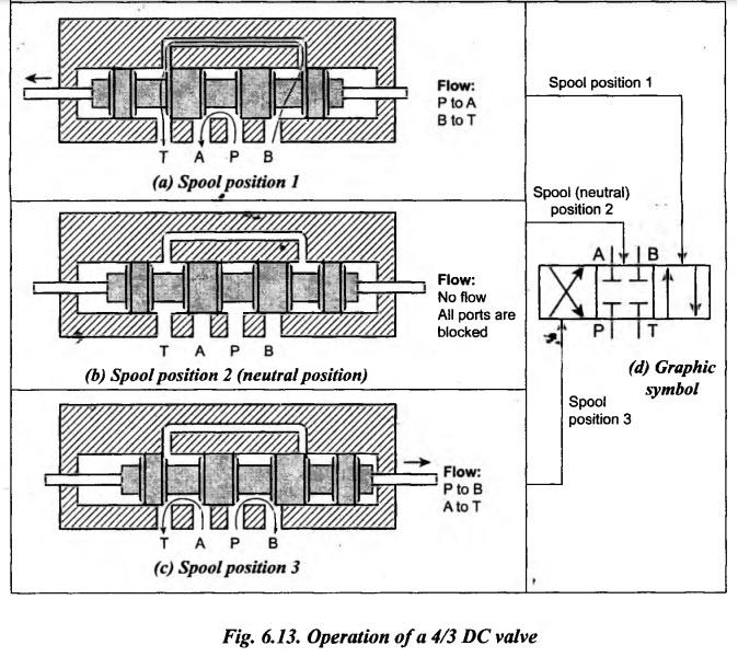
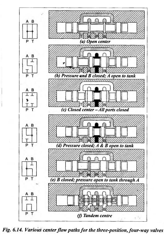
THREE POSITION VALVES The 4/3 valves have 4 ports and 3 distinct positions. 1. Construction and Operation The construction and operation of a typical sliding-spool type 4/3 DC valve is illustrated in Fig.6.13. This valve also has four ports P, A, B, and T. Spool position 1: For the spool position shown in Fig.6.13(a), the fluid can flow from port P to port A and return from port B to port T. Spool position 2: During the neutral position shown in Fig.6.13(b), all the ports are blocked. Spool position 3: For the spool position shown in Fig.6.13(c), the reverse flow is permitted. i.e., fluid can flow from port P to port B and return from port A to port T. 2. Graphic Symbol Fig.6.13(d) represents the graphic symbol for the above 4/3 DC valve. As we discussed, the two extreme positions of a 4/2 control valve controls the two extreme direction of motion of fluid. In 4/3 valves, the third position usually is an intermediate or a centre position. Varieties of centre positions are possible in 4/3 DC valves by suitably designing the spool. Fig.6.14 illustrates some of the widely used centre flow path configurations for 4/3 valves. These centre positions are briefed below : 1. Open Centre: • In open centre type, all ports of the valve P, A, B, and T are open to each other, as shown in Fig.6.14(a). • Advantage : As soon as the cylinder completes its cycle, the open centre DC valve allows the pump flow to return to back the tank (reservoir) at a minimum pressure. This prevents unnecessary heat build-up in the system. • Disadvantage: When the valve is centred, no other cylinder can operate. Therefore, open-centre type valve is used mostly for a single cylinder or single motor circuit. 2. Closed Centre: • In closed centre type, all the ports P, A, B, and T are blocked to each other, as shown in Fig.6.14(c). • Advantage: The closed centre type valve can use the pump flow for other parts of the circuit. Therefore closed typed valves are used when multiple functions are to be accomplished from one source. • Disadvantage: When the valve is in closed centre position, the pump flow cannot be unloaded to the tank. So the hydraulic cylinder or fluid motor cannot be moved. 3. Tandem Centre: • The tandem centre type valve, as shown in Fig.6.14(f), directs the pump flow out of the reservoir port T with the other two working ports A and B closed when in the centre position. • Advantage: Like open centre valve, this type valve also unloads the pump at essentially atmospheric pressure. The application of this design is to permit the flow to be connected to a series of valves for multiple circuits. • Disadvantage: When a number of cylinders are operated from a single source, the pressure differential for each tandem centre valve will be 3 to 4 bar each while the valve is in its centre position. 4. Floated Centre: • The floated centre type valves allow independent operation of cylinders connected to the same power source, as shown in Fig.6.14(b), (d), and (e). • Advantage : This type does not build up any pressure in the cylinder lines. Therefore, there will not be any drifting of cylinders during this condition. • Disadvantage: The load cannot be locked in this position during the neutral position. 3. Applications of Position Valves • Two way directional valves are generally used as shut off valves. Unlike a check valve, the two-way valve can block flow in both directions. • Generally three way directional control valves are used to control single-acting linear actuators. • The four way directional control valves are used to control double-acting actuators. • A three-position valve can be used: (i) to isolate an actuator from the circuit, (ii) to provide a bypass to the reservoir around the actuator, or (iii) to hold an actuator in an intermediate position. 4. Specification of Directional Control Valves The DC valves are usually specified by the following parameters : 1. Rated flow, 2. Rated pressure, 3. Outlet and inlet port size, 4. 3 way or 4 way spool, 5. Open or closed centre application, 6. Spring centred or not, 7. Solenoid type and power, etc.1. 4/3 Directional Control Valves
2. Centre Flow Configurations for Three-Position, Four-Way Valves
Hydraulics and Pneumatics: Unit II: Hydraulic Actuators and Control Components : Tag: : Hydraulic Actuators and Control Components - Hydraulic Actuators and Control Components - Three position valves
Related Topics
Related Subjects

Hydraulics and Pneumatics
ME3492 4th semester Mechanical Dept | 2021 Regulation | 4th Semester Mechanical Dept 2021 Regulation