Theory of Machines: Unit IV: Force Analysis
static force analysis of simple planar mechanisms
Force Analysis - Theory of Machines
The three methods used for static force analysis of mechanisms are: 1. Principle of superposition, 2. Principle of virtual work, and 3. Method of normal and radial components.
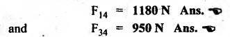
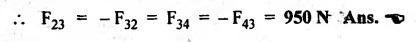
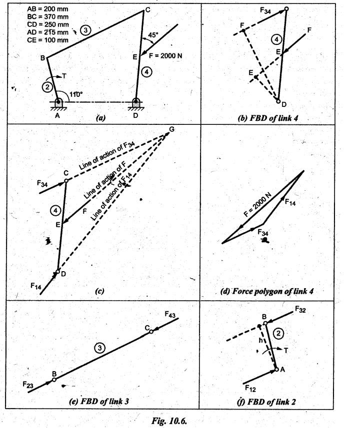
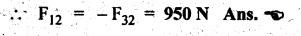
STATIC FORCE ANALYSIS OF SIMPLE PLANAR MECHANISMS The three methods used for static force analysis of mechanisms are: 1. Principle of superposition, 2. Principle of virtual work, and 3. Method of normal and radial components. Now let us discuss about the static force analysis of a mechanism by the principle of superposition. • The principle of superposition states that for liner systems the individual responses to several disturbances or driving functions can be superposed on each other to obtain the total response of the system. • In other terms, in linear systems if a number of loads act on a system of forces, then the net effect is equal to the superposition of the effects of the individual loads taken out at a time. • The step-by-step static force analysis of a four-bar mechanism and a slider-crank mechanism are presented in Examples 10.3 and 10.4 respectively. Example 10.3 A four bar chain mechanism ABCD is shown in Fig.10.6(a). Calculate the required value of torque required (T) and all the constraint forces on links for static equilibrium of the mechanism, if F = 2000 N in the direction shown. The dimensions of linkages are as follows: AB = 200 mm; BC = 370 mm; CD = 250 mm; AD = 215 mm and CE = 100 mm Given data: F = 2000 N; AB200 mm; BC= 370 mm; CD = 250 mm; AD = 215 mm; CE = 100 mm. Solution: 1. First of all, draw the given four bar mechanism with given force F = 2000 N, to some suitable scale (say 1 cm = 100 mm), as shown in Fig.10.6(a). 2. Now draw the free body diagrams for links 4, 3 and 2 with all applied forces, as shown in Figs. 10.6(b), (d), and (e) respectively. 3. Equilibrium of link 4: ■ Link 4 is acted upon by three forces F (completely known), F34 (direction only known and is parallel to link BC), and F14 (completely unknown). ■ Draw the FBD of link 4 as shown in Fig.10.6(b). ■ Extend the lines of action of F and F34 so as to obtain the intersection point G, known as point of concurrency, as shown in Fig. 10.6(c). Now join OD to obtain the line of action of F14. ■ To find F14 and F34 : Using F and lines of action of F14 and F34, draw the force polygon, to some suitable scale (say 1 cm = 1000 N), as shown in Fig.10.6(d). We know that for equilibrium the force polygon must close. By measuring the closing sides of the force polygon to the chosen scale, we get 4. Equilibrium of link 3: Link 3 is a two force member (F23 and F43), as shown in Fig.10.6(e). • Linear systems are those in which effect is proportional to cause. This means that the response or output of a linear system is directly proportional to the input of the system. 5. Equilibrium of link 2: Link 2 is acted upon by two forces F12, F32, and a torque T, as shown in Fig.10.6). The link 2 is in equilibrium only when force F12 = F32. Both forces F32 and F12 being parallel and opposite to each other. From FBD of link 2, torque applied, T = F32 × h = F12 × h By measurement to the chosen scale, h = 200 mm. Example 10.4 In Fig.10.7(a), a slider-crank mechanism is shown. The value of force applied on slider 4 is 3000 N. Determine the forces acting on various links and also calculate the driving torque T. The linkage dimensions are: AB = 100 mm; BC= 300 mm; Given data: F = 3000 N; AB = 100 mm; BC = 300 mm; Solution: 1. First of all, draw the given slider-crank mechanism with given force F = 3000 N, to some suitable scale (say 1 cm = 100 mm), as shown in Fig.10.7(a). 2. Now draw the free body diagrams of links 2, 3 and 4 with all applied forces, as shown in Figs. 10.7(b), (c), and (d) respectively. 3. Equilibrium of link 4: Link force is acted upon by three forces F (completely known), F14 and F34 (magnitude unknown, but directions are known). ■ Using the known lines of action of all the three forces, draw the force polygon to some suitable scale (say 1 cm = 1000 N), as shown in Fig. 10.7(e). ■ We know that for equilibrium the force polygon must close. By measuring the closing sides of the force polygon to the chosen scale, we get 4. Equilibrium of link 3: Link 3 is a two-force member (F23 and F43), as shown in Fig.10.7(c). 5. Equilibrium of link 2: Link 2 is acted upon by two forces F12 and F32, and a torque T, as shown in Fig. 10.7(b). The link is in equilibrium only when force F12 = F32. From Fig.10.7(b), torque applied, T = F32 × h = F12 × h By measurement to the chosen scale, h = 100 mm1. Principle of Superposition

![]() BAC = 60°
BAC = 60°![]() BAC = 60°.
BAC = 60°.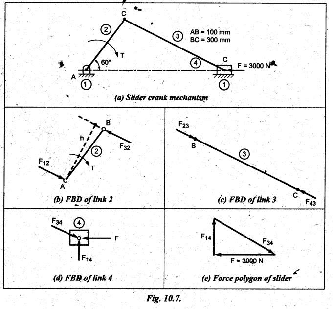


Theory of Machines: Unit IV: Force Analysis : Tag: : Force Analysis - Theory of Machines - static force analysis of simple planar mechanisms
Related Topics
Related Subjects

Theory of Machines
ME3491 4th semester Mechanical Dept | 2021 Regulation | 4th Semester Mechanical Dept 2021 Regulation