Manufacturing Technology: Unit IV: CNC Machines
spindle drives in CNC machines
CNC Machines - Manufacturing Technology
The spindle drive system usually uses electric motors although hydraulic motors are sometimes used for large machine tools.
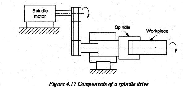
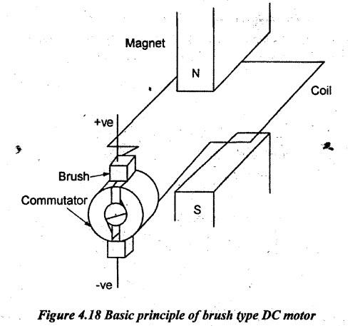
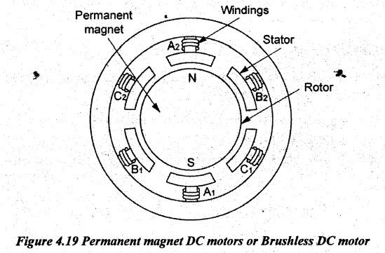
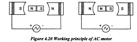
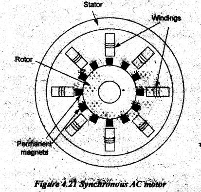
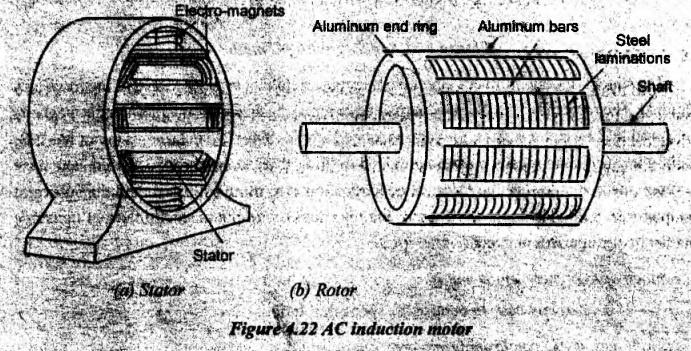
SPINDLE DRIVES IN CNC MACHINES The spindle drives are used to provide angular motion to the workpiece or a cutting tool. Figure 4.17 shows the components of a spindle drive. These drives are essentially required to maintain the speed accurately within a specified power limit which will enable machining of a variety of materials with variations in material hardness. The speed ranges can be from 10 rpm to 20,000 rpm. The spindle drive system usually uses electric motors although hydraulic motors are sometimes used for large machine tools. An electric motor is an electric machine that converts electrical energy into mechanical energy. Most electric motors operate through the interaction between an electric motor's magnetic field and winding currents to generate force within the motor. Many modern machine tools employ DC spindle drives. DC drives were very popular with speed control using voltage variation. By varying the voltage input, their speeds are infinitely variable as they rotate and a constant cutting speed can be maintained. AC motors are also used as spindle drives in many CNC machines. Nowadays, AC drives are preferred to DC drives due to the advent of microprocessor-based AC frequency inverter. The use of AC motors usually involves a stepped drive, it means, a series of spindle speeds will be available and the selection of a particular speed may involve switching from one speed range to another speed range. The advantage of using AC drive for spindle is that it can also be used for positioning the spindle axis in turn mill centres. The classification of spindle drives with type of controller for each type is as follows. High overload capacity is also needed for unintended overloads on the spindle due to an inappropriate feed. It is desirous to have a compact drive with highly smooth operation. Modern spindle drive and bearing designs are now allowing high-speed machining using more than ten thousand rpm. Researchers have developed fluid or air bearing high-speed spindle that provides higher stiffness, better running accuracies, full range of operation with high HP, lower runout, better dampening and lower vibration, along with unlimited bearing life. These aerostatic bearings uses a spindle shaft runs on a film of air. The machine spindle becomes the motor shaft running on this film of air. The motor is coupled either directly or through a gear box or belt drive to the machine spindle. Many machines have a final belt drive which is quiet and it produces less vibration than a geared drive. Two types of electrical motors are commonly used for spindle drives as follows. (a) Direct Current (DC) motors 1). Permanent magnet type 2) Electromagnet type a) Shunt wound b) Series wound c) Compound wound d) Separate wound. (b) Alternating Current (AC) motor 1) Induction motors 2) Synchronous motors. Direct current (DC) motors allow the precise control of the speed over a wide operating range by manipulating the voltage applied to the motor. They are well suited for driving the axes of small-to medium-sized NC machines and robots. DC motors are also used to drive the spindle in lathes and milling machines when a continuous control of the spindle speed is desired. DC motors work based on the principle that "when a current carrying conductor is placed in a magnetic field, it experiences a force. When a conductor moves in a magnetic field, an e.m.f. is induced." (i) Brush type DC motor: A typical brushed motor consists of an armature coil, slip rings divided into two parts, a pair of brushes and horse shoes electromagnet as shown in Figure 4.18. A simple DC motor has two field poles namely a north pole and a south pole. The magnetic lines of force extend across the opening between poles from north to south. The coil is wound around a soft iron core made of magnetic material is called armature and it is placed in between magnet poles. These electromagnets receive electricity from an outside power source. The coil ends are connected to split rings or commutator. The carbon brushes are in contact with the split rings. The brushes are connected to a DC source. Here, the split rings rotate with the coil while the brushes remain stationary. When the electric current flows through the armature conductors placed in the magnetic field, it experiences a force which causes the armature to rotate. This force is called torque. This torque will cause the armature to turn until its magnetic field is aligned with the external field. Once aligned the direction of the current in the windings on the armature reverses, thereby reversing the polarity of the rotor's electromagnetic field. A torque is once again exerted on the rotor, and it continues spinning. The change in direction of current is facilitated by the split ring commutator. The main purpose of the commutator is to overturn the direction of the electric current in the armature. The commutator also aids in the transmission of current between the armature and the power source. Advantages of brushed DC motor: • The design of the brushed DC motor is quite simple • Controlling the speed of a Brush DC Motor is easy • It is cost effective. Disadvantages of brushed DC motor: • It needs high maintenance. • Performance decreases with dust particles • It is less reliable in control at lower speeds • The brushes wear off with usage. (ii) Permanent magnet DC motors or Brushless DC motor: In permanent magnet motors, the stator fields are provided by permanent magnets as shown in Figure 4.19 which require no external power source. The rotor can be of a ceramic permanent magnet type. The brushes and commutator are eliminated and the windings are connected to the control electronics. Here, the conductor is fixed and the magnet moves. This type of motor is lighter and smaller than other equivalent DC motors because the field strength of permanent magnets is high. These motors are easily reversed by switching the direction of the applied voltage because the current and field change direction only in the rotor. It is ideal in control applications because of the linearity of its torque-speed relation. When a permanent magnet motor is used in a position or speed control application with sensor feedback to a controller, it is referred to a servomotor. Advantages of brushless DC motor: • More precise due to computer control • More efficient. • No sparking due to absence of brushes • Less electrical noise • No brushes to wear out • Electromagnets are situated on the stator and hence, it is easy to cool • Motor can operate at speeds above 10,000 rpm under loaded and unloaded conditions • Responsiveness and quick acceleration due to low rotor inertia. Disadvantages of brushless DC motor: • Higher initial cost • Complex due to presence of computer controller • Brushless DC motor also requires additional system wiring in order to power the electronic commutation circuitry. An AC motor is an electric motor driven by an alternating current (AC). The AC motor commonly consists of the following two basic parts. • An outside stationary stator having coils supplied with alternating current to produce a rotating magnetic field, and • An inside rotor attached to the output shaft producing a second rotating magnetic field. The working principle of AC motor is shown in Figure 4.20 by considering the rotor to be a permanent magnet. Current flowing through conductors energizes the magnets and develops N and S poles. The strength of electromagnets depends on current. First half cycle current flows in one direction and in the second half cycle, it flows in opposite direction as AC voltage changes the poles alternate. (i) AC synchronous motors: A synchronous motor is an AC motor which runs at constant speed fixed by frequency of the system. These motors have the rotor (which is connected to the load) rotating at the same speed as the speed of rotation of the stator current. In other words, these motors don't have slip with respect to the stator current. The stator consists of a group of individual wounded electro- magnets arranged in such a way that they form a hollow cylinder as shown in Figure 4.21. Stator The stator winding produces a rotating magnetic field that is proportional to the frequency supplied. The rotor may be a permanent magnet or it may be an electromagnet. As the magnetic field I produced by stator rotates, the rotor is rotated with it. Since a synchronous motor has little starting torque, some means must be provided to bring it up to synchronous speed. The most common method is to start the motor åt no load, allow it to reach full speed and then energize the magnetic field. The magnetic field of the rotor locks with the magnetic field of the stator and the motor operates at synchronous speed. Advantage of AC synchronous motors: It is relatively easy to control the speed of rotation. Disadvantages of AC synchronous motors: • It is costly. • The power decreases with rpm below the base speeds. • It involves large dimension and weight. (ii) AC induction motors: The main parts in an AC induction motor are rotor (rotating element) and stator (stationary element that generates the magnetic flux). The rotor construction looks similar to a squirrel cage, hence, it is called squirrel cage induction motor. Figure 4.22 illustrates the rotor and stator constructions. The rotor is made of copper or aluminum bars and it fits into slots in end rings to form complete electrical circuits. Induction motors can be classified into two types: (a) Single-phase induction motor (b) Three-phase induction motor A single-phase induction motor has only one stator winding. This winding generates a field which merely pulsates instea Isates instead of routing. When the rotor is stationary, the expanding and collapsing star fields induce electric current in the rotor. These currents generate a rotor field opposite. similar to the stator. The opposition of the field exerts a turning force on the upper and lower parts of the rotor trying to turn it 180° from its position. Since these forces are exerted through the center of the rotor, the turning force is equal in each direction. The motor is not self-starting. Hence, a number of methods are used to make the motor self-starting. One method is to use an auxiliary starting winding to give an initial push to rotor. The rotor rotates at the speed determined by the frequency of alternating current applied to the stator. Thus, for a constant frequency supplied, the magnetic field will alternate at this frequency: "This speed of retation of magnetic held is known as synchronous speed. The rotor differs from this frequency of rotation about 1% to 3% and this difference is termed as slip. Three phase induction motors are similar to single phase induction motor but the stator has three windings located 120° apart and they are connected to the lines of supply. The three- phase current produces a rotating magnetic field in the stator. This rotating magnetic field causes a magnetic field to be set up in the rotor also. The attraction two magnetic fields causes the rotor to turn. As a result. full cycle of the current. The direction of rotation cai line connections. Advantages of AC induction motors repulsion between these plote's one full rotation in one Interchanging any two of • It has a simple design, low inalal cost. consration almost unbreakable • The operation is simple with less maintenance (as there are no brushes) • The efficiency of these motors is reasonably good The control gear for the simple and reliable opera Disadvantages of AC induction motors: • The speed control of these motors of their efficiency • As the load on the motor increases the speed decreases • The starting torque is inferior when compared to DC motors.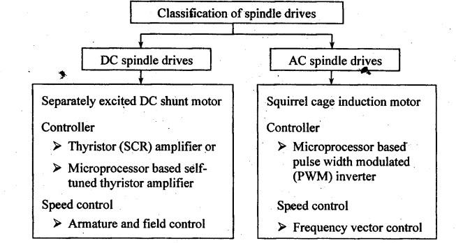
1. DC Motors
2. AC Motors
Manufacturing Technology: Unit IV: CNC Machines : Tag: : CNC Machines - Manufacturing Technology - spindle drives in CNC machines
Related Topics
Related Subjects

Manufacturing Technology
ME3493 4th semester Mechanical Dept | 2021 Regulation | 4th Semester Mechanical Dept 2021 Regulation