Hydraulics and Pneumatics: Unit III: Hydraulic Circuits and Systems
speed control circuits
Hydraulic Circuits and Systems - Hydraulics and Pneumatics
As we have discussed in Section 6.20, flow control valves are used to control the speed of hydraulic cylinders.
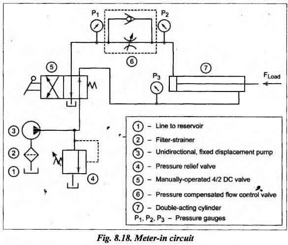
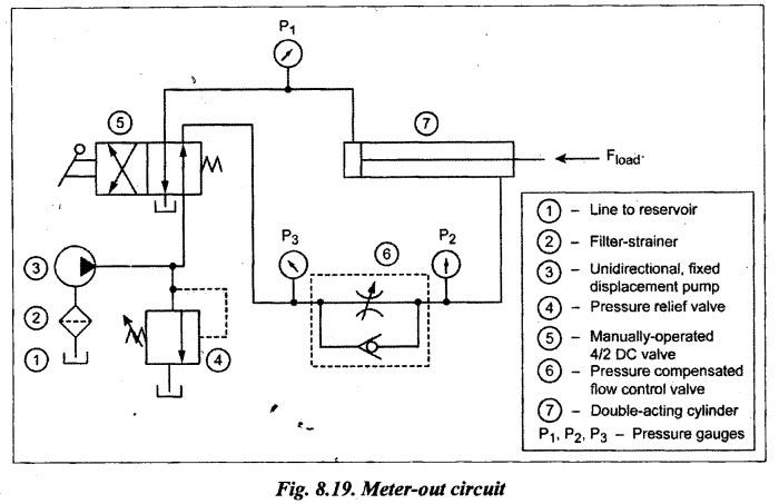
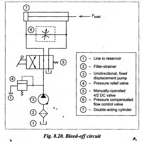
SPEED CONTROL CIRCUITS • As we have discussed in Section 6.20, flow control valves are used to control the speed of hydraulic cylinders. It should be noted that the location of flow control valve with respect to other components in a circuit will have effect on the characteristics of the circuit performance. • The three basic types of locations of the flow control valve in any hydraulic circuit are: 1. Meter-in circuit, 2. Meter-out circuit, and 3. Bleed-off circuit Now we shall discuss meter-in and meter-out types of speed control of hydraulic cylinders in the following sections. 1. What is Meter-in Circuit? • In meter-in type, the speed control of hydraulic cylinder, flow control valve is located in between the pump and the actuator (piston side connection). Thereby this circuit controls the amount of fluid flowing into the cylinder. • Applications: The meter-in circuits are generally used when the external load opposes the direction of motion of the hydraulic cylinder. An example of this situation is the case of a hydraulic table feed on a surface grinder. 2. Circuit Fig.8.18 illustrates a meter-in circuit that can be used to control the speed of a hydraulic cylinder using a flow control valve. This circuit uses a manually-operated spring-offset 4/2 DC valve and a flow control valve. 3. Operation Extension: When the 4/2 DC valve is mechanically shifted to its left mode, oil flows from the pump to the blind end of the cylinder via the flow control valve. This pump flow extends the cylinder. Here it can be noted that the extending speed of the cylinder depends on the setting of the flow control valve. Thus the extending speed of the cylinder can be increased or decreased just by regulating the flow of fluid in the flow control valve. Retraction: When the 4/2 DC valve is shifted to its right mode, oil flows from the pump to the rod end of the cylinder and hence the cylinder retracts. The oil from the blind end of the cylinder drains back to the oil tank through the check valve as well as the flow control valve. 1. What is Meter-out Circuit? • In meter-out type of speed control of hydraulic cylinder, the flow, control valve is located in between the actuator (rod side connection) and the oil reservoir. Thereby this circuit controls the fluid flowing out of the actuator. • Applications: The meter-out circuits are commonly used when the external load acts in the square direction of motion of the hydraulic cylinder. An example of this situation is the case of a load acting downward on the piston rod of a vertical cylinder. To avoid the erratic downward motion of the load, a back pressure is maintained in the exhaust side of the cylinder by using meter-out circuit. 2. Circuit Fig.8.19 illustrates a meter-out circuit to control the speed of a hydraulic cylinder. 3. Operation The operation meter-out circuit is very much similar to that of the meter-in circuit. The only difference is that meter-out flow control system controls the oil flow rate out of the cylinder. In other words, meter-out circuit controls the retracting speed of the cylinder. 1. What is Bleed-Off Circuit? • In bleed-off type speed control of hydraulic cylinder, the flow control valve is located in between the pressure line and return line (either before the DC valve or after the DC valve). Thereby this circuit controls the fluid by bleeding off the excess not needed by the actuator. • This method is also known as by-pass control method. • Applications: Bleed-off circuits are employed where pressure is reasonably constant and precise speed control is not the prime requirement. These circuits are widely used in broaching machines, shapers, planers, etc., where a large quantity of fluid is to be used, and small percentage is by-passed. 2. Circuit Fig. 8.20 illustrates a bleed-off circuit to control the speed of a hydraulic cylinder. In this circuit, flow control valve is placed after the directional control valve. 3. Operation The bleed-off circuit controls neither the flow going to the actuator nor flow returning from the actuator, but it controls the diverted part of fluid to control the flow. The cylinder speed is determined by the difference between the pump deliver flow and the flow being directed to the tank through the flow control valve.1. Meter-in Circuit
2. METER-OUT CIRCUIT
3. Bleed-Off Circuit
Hydraulics and Pneumatics: Unit III: Hydraulic Circuits and Systems : Tag: : Hydraulic Circuits and Systems - Hydraulics and Pneumatics - speed control circuits
Related Topics
Related Subjects

Hydraulics and Pneumatics
ME3492 4th semester Mechanical Dept | 2021 Regulation | 4th Semester Mechanical Dept 2021 Regulation