Manufacturing Processes: Unit IV: Sheet Metal Processes
Special forming processes
Working Principle, Operations, Advantages, Disadvantages, Applications
Generally, forming process is done by pressing the form tool over the blank to obtain the required shape.
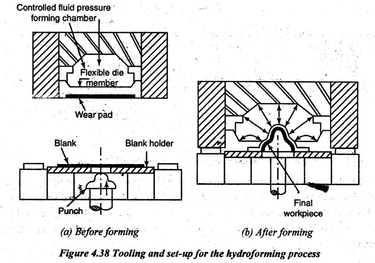
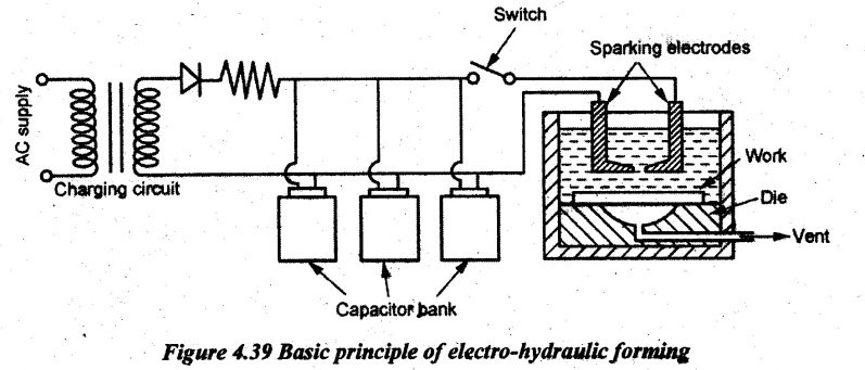
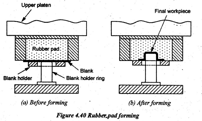
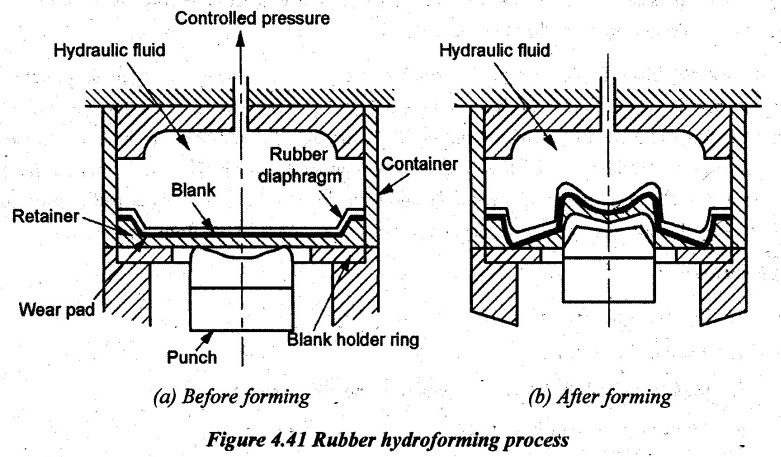
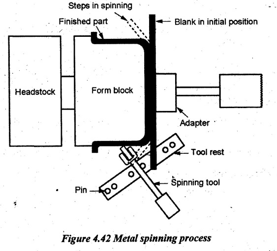
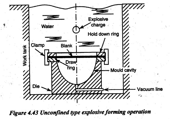
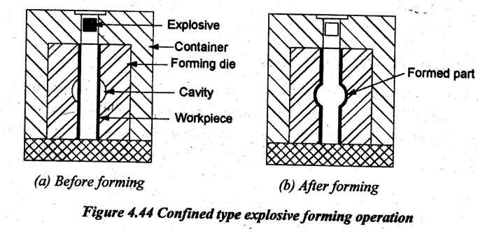
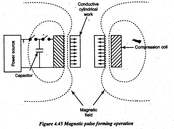
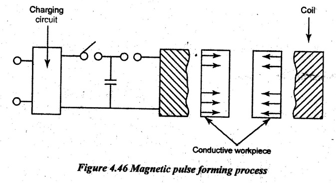
SPECIAL FORMING PROCESSES Generally, forming process is done by pressing the form tool over the blank to obtain the required shape. The form tool is actuated by hydraulic cylinder using hydraulic fluid. In the case of mating die method, the sheet metal is placed over the lower die and its ends are fixed on movable grippers. Then, the upper die is moved towards the blank. If the female or upper die is actuated by any other means except a hydraulic cylinder in the forming process, it is called special forming process. There are various special forming processes as follows: 1. Hydroforming 2. Rubber pad forming 3. Metal spinning 4. Explosive forming 5. Magnetic pulse forming 6. Peen forming 7. Superplastic forming Hydroforming is a drawing process. This forming process is carried out in two ways. They are 1. Hydro-mechanical forming and 2. Electro-hydraulic forming 1. Hydro-mechanical forming: In this type of forming process, the punch is connected to the lower die called male die. The required shape of inner configuration is made on the punch. A rubber diaphragm or seal is used for making perfect sealing between male and female die. This seal is placed across the bottom of the pressure forming chamber. The pressure-forming chamber is filled with a hydraulic fluid. Thẹn, the blank is correctly positioned over the male die or lower die. Now, the pressure forming chamber called dome is lowered over the blank in such a way that the dome is made to just contact with the blank. After this, hydraulic pressure is applied over the blank. Simultaneously, the punch is pushed into the blank. The pressure applied by the hydraulic fluid is continuously increased. Due to this, the blank metal flows around the punch to form the required shape. The inverted shape of the punch is made on the blank. Convex shape of the punch is made as concave shape on the blank and vice versa. After forming the required shape, the chamber pressure is released. Then, the chamber is raised from the blank. Finally, the blank is stripped out from the punch. In this case, the required shape of the blank is obtained only by drawing rather than by bending. Also, the blank metal is displaced due to plastic flow instead of stretching. Advantages: 1. Thinning of metal, spot stresses and springback are drastically reduced or completely eliminated. 2. It is used for mass production because the work performed per operation is high. 3. Tool changing can be rapidly done. 4. Complicated contours can also be made. 5. Sharp corners are also possible. 6. All type of sheet metals can be handled. 7. Due to uniform flow of metal between punch and pressure chamber, the mechanical and physical properties are improved. 8. Tolerance of up to 0.005 mm/mm is practically possible. 2. Electro-hydraulic forming process: The working principle of metal forming process is similar to hydro-mechanical forming process. But, the applied pressure over the blank differs because the pressure inside the pressure forming chamber is produced by electrical means. The arrangement of this electro hydraulic forming system is shown in Figure 4.39. When the supply is given to electrical circuit, a high energy is discharged through a bank of capacitor to the hydraulic fluid contained in the chamber. The discharged energy in the chamber is in the form of shock waves and pressure. This mechanical energy is used for metal forming operations in the same manner as mentioned in hydro-mechanical forming operations. Advantages: 1. The pressure inside the chamber is high due to combined shock wave and fluid pressure. 2. Time required per operation is low when compared to hydro-mechanical forming. Disadvantages: 1. Energy losses occur between electrical components to hydraulic fluid. 2. Due to shock waves, both drag force and lift force are created. Finally, it results the stagnation pressure in fluid. Rubber pad forming process is also called marform process. This process is mainly used for bending and stretching or drawing operations. This process is also preferred for fewer quantities of different shaped machine parts needed at regular intervals. For facilitating this feature, the different form blocks called punches are arranged at regular intervals along the pressing bed called rubber pad. In rubber forming, one of the dies in a set is made of flexible material such as a rubber or polyurethane membrane. This rubber pad is placed on a ram of a press. The retainers are placed on both sides of the rubber pad. The function of retainer is to apply the essential hydrostatic pressure on the blank and prevents sideward motion. The force applied on the blank by hydraulic cylinder through the ram and rubber pad. First, the blank is placed over the punch called male die. Then, the upper platen called female part is moved to just touch the top surface of the work. After this, the force is applied and the force is gradually increased on the blank through the rubber pad. The blank holder ring is used to distribute the uniform pressure throughout the blank. Thus, the required shape is formed on the sheet metal between male and female parts. Then, the rubber pad is released by moving the ram upwards. Now, the completed shell is stripped out from the punch. Advantages: 1. Process is more economical. 2. Tooling cost is less. 3. Many required shapes can be formed in one rubber pad itself. 4. There is no need of lubricants. 5. No thinning of metal blank takes place. 6. Tool setting time is less. 7. Deeper shells can be drawn. 8. Parts produced are wrinkle-free, shrink flanges and improved shallow shapes. Limitations: 1. Rubber pads will rapidly wear out. 2. Sharp corners cannot be accurately made. Applications: 1. Production of flanged cylindrical and rectangular cups. 2. Production of spherical domes. 3. Production of parallel and tapered wall shells. 4. Production of unsymmetrical shape components. In this process, the force is applied on the blank through a pressurized liquid behind the rubber pad as shown in Figure 4.41. This force is used to form the sheet metal into the required shape. Here, the rubber pad acts as a seal between pressure forming chamber and blank. Due to application of hydrostatic pressure over the rubber pad, the blank is formed into the required shape. In hydroforming process, the hydraulic pressure energy is directly applied over the surface of the blank. In the case of rubber pad forming process, the pressure is applied over the surface of the blank by the rubber pad which is operated by a hydraulic ram. But in this case, the force is applied over the blank in the form of hydraulic pressure but through the rubber pad. Advantage: Hammering action of hydraulic fluid over the blank is avoided. Disadvantage: Pressure loss occurs between hydraulic fluid and rubber pad. Metal spinning, also known as spin forming or spinning, is a metalworking process by which a disc or tube of metal is rotated at high speed and formed into an axially symmetric part. This process produces hollow parts that are typically circular in cross-section. Methods of spinning process: There are two methods used to produce sheet metal parts. 1. Manual spinning 2. Power spinning. 1. Manual spinning: First, the circular sheet metal blank is centered on a lathe which is placed against a form block. The form block is mounted on the headstock of the spinning lathe as shown in Figure 4.42. The blank is tightly held between form block and tail stock spindle. The required contour surface is made on the form block. The pressure is applied by the roller type forming tool which is placed on the tool post of the spinning lathe. The required shape is gradually formed by continuous application of pressure by the roller. During spinning process, some stretching and thinning of material take place. Metal spinning can be done both in cold and hot states. Heat generation due to friction between spinning tool and blank can also be used to retain the plastic state of sheet metal. Spinning speed varies with size, design, type of metal and thickness of sheet metal. Aluminum copper, brass and stainless steel can also be spun in spinning process. This process is mainly suitable for producing conical shape parts and suitable for low volume production. Components produced in this process do not require any trimming or beading operations. For producing more complex shapes, segmental chucks made from cast aluminium, magnesium alloys or hard wood reinforced with cold rolled steel sheets are used. The lubricants of grease, linseed oil and bees wax are used between form tool, and blank during spinning process. Advantages: 1. The parts which are not be drawn by drawing operations can be easily spun. 2. Heat generated due to friction is used to retain the sheet metal in the plastic state. 3. The process is more economical for low volume production. Disadvantages: 1. Thinning takes place during spinning process. 2. More complex shapes require segmental chucks. Finally, it leads to increase in cost. 3. Accuracy and quality of finished products mainly depend on the skill of the operator. 2. Power spinning process: The quality of finished products mainly depends on the skill and experience of the operator. The accuracy of the finished products is also less in manual spinning process. Even though segmental chucks are used for making complex shapes, the metal thickness and contour shapes are restricted in manual spinning. In order to ensure the skill of the operator and reduced machining time, spinning machines are preferred. When the machine is used to control the action of form tool in spinning operation, it is called power spinning. In power spinning process, the action of form tool is controlled either by any tracer mechanism or by Numerical Control (NC) machines. Now-a-days, Computer Numerical Control (CNC) machines are used to change the shape of the contour whenever the existing program needs to be changed. Advantages of power spinning: 1. Time taken to spin the sheet metal is greatly reduced. 2. Thickness more than 1 mm can be easily handled. 3.. Both accuracy and quality can be maintained 4. It is suitable for high volume production. Applications of metal spinning process: Metal spinning process is used for production of ash trays, flower pots, lamp shades, missile and radar units, jet plane components, tanks, air conditioning units and heating plants. Explosive forming process is used for blanking, cutting, expanding, coining, embossing, flanging, powder compacting, drawing, sizing operations etc. Explosives used can be high energy chemicals such as TNT, RDX and Dynamite or gaseous mixtures or propellants. These chemicals are used in various forms such as rod, sheets, granules, liquid, stick etc. According to the placement of explosives, the operations can be divided into the following two categories: 1. Unconfined type or Stand-off technique 2. Confined system or Contact technique 1. Unconfined type or Stand-off technique: In this case, the explosive charge is located at some distance away from the blank and its energy is transmitted through some fluid medium such as water. The water acts as energy transfer medium and ensures uniform transmission of energy. It also muffles the sound of explosion and provides cushioning/ smooth application of energy on the work without direct contact. This technique is used to form blanks into various shapes except welding, hardening, compacting and cutting processes. In this process, the forming of sheet metal is done by generating pressure wave in the fluid. The pressure wave is generated by detonating enough quantity of explosives. The blank being formed is placed against the female die as shown in Figure 4.43. This female die has the required configurations. This entire set up of female die and blank is placed inside the work tank. The work tank contains water to receive vibrations in the form of pressure wave. The charge or explosives are also placed inside the work tank. The work tank should be perfectly insulated to avoid the heat transfer from system to surrounding. Now, the explosive charge is ignited by the detonator. Due to this, a high-pressure energy is released in the form of waves and pulse (vibration) in the water contained in the work tank. These pressure waves are applied over the blank to obtain the required shape of female die. The applied pressure by this process may vary from several hundred to thousands of kg/cm2 and around 120 m/s displacement velocity. 2. Confined system or Contact technique: In this case, the explosive charge is directly located over the blank. Hence, the pressure pulse or shock wave produced is in direct contact with the workpiece. The energy is directly applied on the work without any water medium. The workpiece used here is usually in a tubular form. This operation is mainly used for welding, hardening, bulging, flattering, compacting and cutting operations. Figure 4.44 illustrates the confined system or contact technique of explosive forming. The tubular workpiece is placed in the die cavity which is having the form to be produced. When the explosive is ignited, the pressure energy created by the explosive directly hit the tube and collapses it into the die cavity. Thus, the required shape is formed. Advantages of explosive forming: 1. Capital investment is less and presses are not required. 2. Only one die is enough to form the sheet metal. 3. The required shapes of components are formed in one stroke. 4. Ultimate strength and yield strength of sheet metals are improved. 5. Large and complex shapes can also be handled. Disadvantages of explosive forming: 1. Highly trained operators are needed. 2. Operation is noisy. 3. Explosives must be carefully handled according to the regulations of the government. 4. Dies must be larger and thicker to withstand shocks. Applications of explosive forming: This process is mainly used for producing aerospace components. Process variables of explosive forming: 1. Type and amount of explosive: a wide range of explosives is available. 2. Medium used to transmit energy: Water is most widely used. 3. Stand-off distance (SOD): It is the distance between workpiece and explosive. Optimum SOD must be maintained. 4. Work size 5. Work material properties 6. Vacuum in the die. In this process, the required shape of the sheet metal is obtained by specially designed magnetic coil. The basic principle is that the required shape is obtained by discharging a capacitor through a coil over a period of microseconds on the blank. During this discharge, the magnetic flux densities of the order of hundreds of kilogausses can be produced. The basic circuit consists of energy storage capacitor, switch, coil and power source. The current through the coil produces high intensity magnetic field between coil and workpiece. Due to eddy current in the blank, the magnetic field is restricted over the surface of blank. Due to the interaction of eddy current on the blank, the applied magnetic field creates an inward force on the workpiece. Since the coil is placed rigidly, the repelling force between workpiece and coil is high. So, the blank is forced against a coil. Properly designed coils can be used for compression, expansion or forming the blank to concentrate the current. Hence, the force in certain regions of the blank is shaped by utilizing massive conducting structure by a flux concentrator device which is not connected directly to the basic coil. This process is most suitable for copper, aluminium, silver and gold. For non-conducting material, the force must be generated by using conductive material between oil and blank for efficient operation. The coil should be good and perfectly fit in the blank. Advantages: 1. This process is carried out with uniform rate of forming. 2. It is also a better process than convention process for certain materials. 3. The surface finish of the process is excellent. 4. Time of operation is less as compared to conventional process. Disadvantages: 1. Non-conducting materials are not processed without aid of conducting materials. 2. It is limited for sheet metal forming process not an forming bulk material. Applications: 1. Both compression and expansion of circular bar can be carried out. 2. Producing bulging of tube, shrinkage of tube and attaching tubes at end fitting without leaking are possible. 3. Forming the torque joints, forging of structural joints between tubes and fitting are easily formed. 4. It is used for instrument gear assembly, embossing, sizing of cups etc. This process is also called shot peening or free-forming technique. In this process, a stream of balls or metal shots is blasted against the surface of the sheet metal blank to be made into the required shape. The peen forming process does not require any die and forming press. The part to be made by the sheet metal placed on a form block as shown in Figure 4.47 or it may be suspended from support. Then, the stream of small steel balls is suddenly forced with very high velocity against the surface of the blank. This process is used to form various irregular contour surfaces of aluminium sheet and plates even the required shape can be obtained by placing the blank on a table or by suspending from a support to blast. Advantages: 1. Complex contours can be easily produced. 2. Peening is also used as salvage operations for correcting bent or distorted parts. 3. This process does not require any die and punch. Disadvantages: 1. It requires longer time for forming the required shape. 2. It requires additional devices for forcing out metal shots. Applications: 1. It is used for producing honeycomb panels such as aircraft wings and large tubular shapes. 2. This process provides smoothing and complex curvature of aircraft wings. Superplastic forming is a process in which a sheet of metal is clamped between a die cavity and a plate which are kept at the suitable temperature. Gas pressure is applied to deform the sheet by forcing it against the walls of the die cavity, under suitable stress and deformation rate. Superplastic forming (SPF) of sheet metal has been used to produce very complex shapes and integrated structures used in the aircraft and automobile industries. Superplasticity is the ability of certain materials to undergo extreme elongation at the proper temperature and strain rate. SPF can produce parts that are impossible to form using conventional techniques. The process typically conducted at high temperature and under controlled strain rate which can give a ten-fold increase in elongation as compared to conventional processes. Components are formed by applying gas pressure between one or more sheets and a die surface, causing the sheets to stretch and fill the die cavity. The evolution of pressures must be closely controlled during the process since the alloys of interest only exhibits superplastic behaviour for certain temperature dependent range of strain rates. Specific alloys of titanium, stainless steel, and aluminum are commercially available with the fine-grained microstructure and strain rate sensitivity of flow stress that are necessary for superplastic deformation. Working: During SPF process, the material is heated to SPF temperature within a sealed die as shown in Figure 4.48. Inert gas pressure is then applied at a controlled rate by forcing the material to take up the shape of the die pattern. The flow stress of the material during deformation increases rapidly with increase in strain rate. Superplastic alloys can be stretched at high temperature by several times of their initial length without breaking. Some of the materials developed for superplastic forming are: 1. Bismuth-tin (200% elongation) 2. Zinc-aluminum 3. Titanium (Ti-6Al-V) 4. Aluminum (2004, 2419, 7475) 5. Aluminum-lithium alloys (2090, 2091, 8090) Loading: The blank is loaded in the form die. The hot press heats the die and blank to the material. super-plastic temperature. This method involves in hot forming up to 1000°C superplastic alloys by using an inert gas pressured up to 50 bar. Combined with diffusion bonding, this process allows the forming of honeycomb structures made of several sheets in a single operation. Forming: Once the temperature is reached, it is accurately controlled while the gas pressure slowly inflates the blank as shown in Figure 4.48 (c). The gas keeps inflating the part to fit in the die. The material at the super-plastic temperature can allow up to 500% elongation. Release: At the end of the forming cycle, the part perfectly conforms to the die even in its smallest details as shown in Figure 4.48 (d). Advantages of SPF process: Superplastic forming technology offers the potential to reduce the weight and cost of automotive structural components for advanced vehicle applications. The main advantages of this process are: 1. It is a one step process. 2. The process can be used to form complex components in shapes that are very near the final dimension. 3. Higher material elongations are possible. 4. It eliminates unnecessary joints and rivets. 5. It reduces subsequent machining operations. 6. It minimizes the amount of scrap-produced. Applications: The process is increasingly being applied in the aerospace industry as a way of manufacturing very complex geometries. It is also used in. (i) forming of automotive body panels. (ii) forming of aircraft frames and skins. (iii) diaphragm forming of plastics. (iv) complex shaped parts such as window frames, seat structures etc. Micro forming involves forming of parts and features with dimensions below 1 mm. It is a recent area of research in the wide field of metal forming technologies which is expanding the limits for applying metal forming towards micro technology. With the global trend of product miniaturization, the market demands for micro-parts are increasing tremendously. Thus, the state-of-the-art micro-manufacturing processes for the fabrication of micro-parts become critical. - The major sheet metal processes for micro forming are shearing, blanking, bending, stamping, deep drawing (including mechanical and hydro-mechanical), hydro-forming, stretching forming, super-plastic forming, age forming, spinning, explosive forming, incremental forming, etc. Similar to conventional sheet metal, the mechanical properties of the materials such as elasticity, plasticity, stress strain relations, strain rate, work hardening, temperature effect, anisotropy, grain size and residual stress involve in analysing the deformation of micro- forming products. The effects of grains sizes, orientations and grain boundary properties are more significant in micro-sheet forming while considering the effects of overall stress-strain relationship, sheared-section qualities, springback phenomenon, stress relaxation, etc. Generally, the micro forming processes are used to make the followings parts: ● Micro-gears and micro-shafts for micro-mechanical devices ● Connector pin ● IC chip lead frame and IC sockets ● Miniature fasteners ● Micro-meshes for masks and optical devices ● Micro-springs for micro-switches ● Micro-cups for electron guns and micro-packaging ● Micro-laminates for micro-motor and fluidic devices ● Micro-knives for surgery ● Hard disc drives ● Sensors.1. Hydroforming Process
2. Rubber Pad Forming Process
3. Rubber Hydroforming Process
4. Metal Spinning Process
5. Explosive Forming Process
6. Magnetic Pulse Forming Process
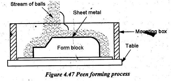
7. Peen Forming Process
8. Superplastic Forming Process
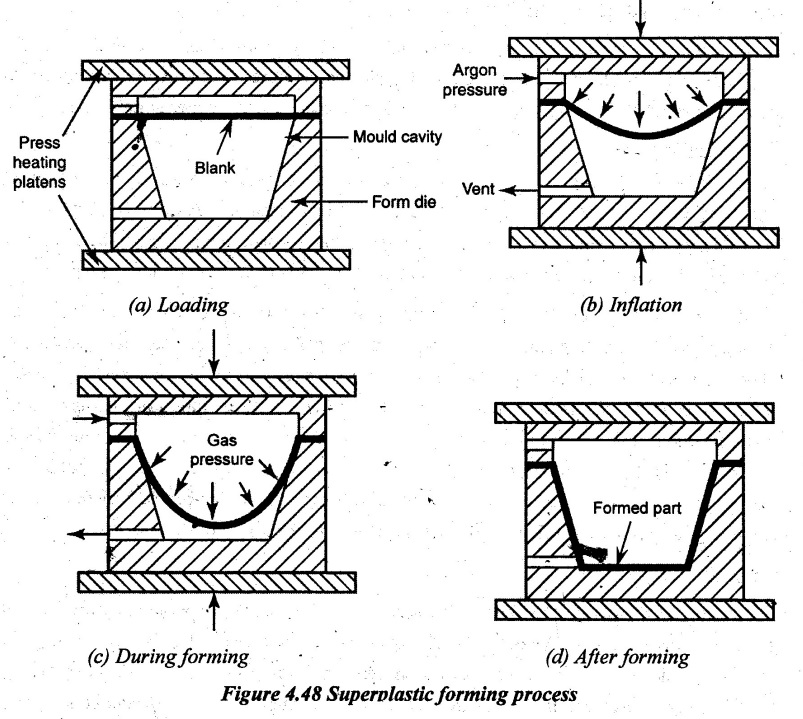 Superplastic forming process:
9. Micro Forming in Sheet Metal Processes
Manufacturing Processes: Unit IV: Sheet Metal Processes : Tag: : Working Principle, Operations, Advantages, Disadvantages, Applications - Special forming processes
Related Topics
Related Subjects
Manufacturing Processes
ME3393 3rd semester Mechanical Dept | 2021 Regulation | 3rd Semester Mechanical Dept 2021 Regulation