Manufacturing Technology: Unit II: Turning Machines
special attachments
Turning Machines - Manufacturing Technology
Most of the lathe operations discussed so far allow for general purpose machining operations to be carried using a centre lathe.
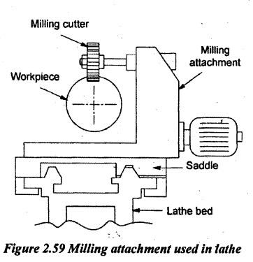
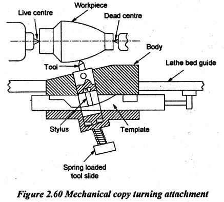
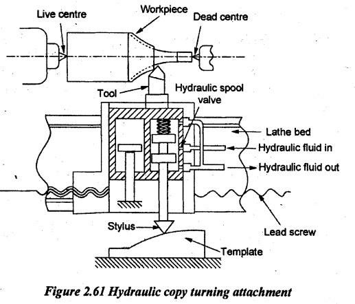
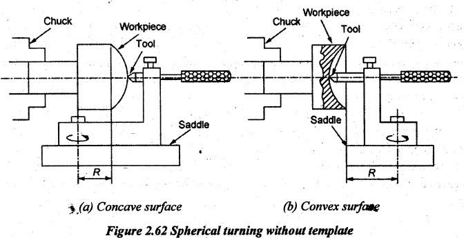
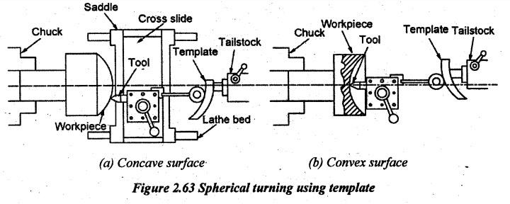
SPECIAL ATTACHMENTS Most of the lathe operations discussed so far allow for general purpose machining operations to be carried using a centre lathe. In addition to these operations, it is possible to provide some special attachments to the capability of lathe so that the lathe can be used for special machining applications using these attachments. The taper turning attachment discussed earlier for producing tapers on cylindrical workpieces is one such attachment. Moreover, milling and grinding operations can also be performed on lathes by using special attachments. Milling is the process of removing metal by moving the work against a rotating cutter. Milling cutters have multipoint cutting edges. Milling attachment is used in lathes to carry out milling operations. The attachment is provided with a motor, a small gear box and a separate spindle where the milling cutter could be located as shown in Figure 2.59. It is attached to the cross slide or saddle and replacing the compound slide. The milling cutter an normally be fed in all three directions, thus permitting any type of milling operations. Milling attachments are generally used for making flat surfaces, straight and helical grooves, splines, long and deep screw threads, worms etc. in centre lathes by using suitable milling cutters. Milling operations can be carried out in two methods depending upon the form of profiles. 1. For cutting grooves or keyways: Here, the work is held on the cross slide and milling cutter is held ba chuck using the special attachment. Then, the depth of cut is given by a vertical slide provided on the attachment. 2. For cutting multiple grooves and gear wheel: In this case, the work is held stationary between centres. The attachment is mounted on the cross slide on the carriage which is driven by a separate electric motor. The feeding is given by the carriage and the vertical movement is given by the provision made on the attachment. Similarly, a number of grooves are made on the periphery of the work by rotating the work. For cutting gears, a universal dividing head is fitted on the rear end of the headstock spindle to divide the work equally. Grinding is the operation of removing metal in the fine form of chips. It is done by moving the work against a rotating abrasive wheel. This abrasive wheel is known as grinding wheel. Grinding attachment is very similar to milling attachment. But in the former, there is no gear box and the spindle speed is much higher as needed for grinding operation. Both external and internal grindings can be cut by using special attachments on a lathe. The work is held between centres or on a chuck and rotated for grinding external surfaces. For grinding internal surfaces, a work is held on a chuck or faceplate. Then feeding is given by moving the carriage and the cross slide is moved for giving the depth of cut. Generally, grinding is done on lathes using attachments for finishing workpieces, sharpening a cutting tool and sizing workpieces to close tolerance.. Sometimes, it is required to machine the complex contours on the work which require the feeding of the tool in two axes (x and y axes) simultaneously similar to taper turning. For such purposes, copy turning attachment is useful. In this, the cross slide is directly driven by a stylus which can trace a master template for the actual contour to be produced. There are two common types of copy turning: (a) mechanical type (b) hydraulic type (a) Mechanical copy turning attachment A simple mechanical type copy turning attachment is shown in Figure 2.60. The entire attachment is mounted on the saddle by removing the cross slide. The template replicating the job-profile desired is clamped at a suitable position on the bed. The stylus is fitted in the spring loaded tool slide. When the tool slide travels longitudinally along with saddle, the stylus is moved in the transverse direction according to the template profile. It enables the cutting tool to produce the same profile on the job. (b) Hydraulic copy turning attachment In the mechanical system, the heavy cutting force is transmitted at the tip of the stylus which causes vibration, large friction and faster wear and tear. Such problems are almost absent in hydraulic copying where the stylus works simply as a spool valve against a light spring and it is not affected by the cutting force. Hydraulic copying attachment is costlier than the mechanical type but it works much smoothly and accurately. The cutting tool is rigidly fixed on the cross slide which also acts as a valve-cum-cylinder as shown in Figure 2.61. As long as the stylus remains on a straight edge parallel to the lathe bed, the cylinder does not move transversely and the tool causes straight turning. As soon as the stylus starts moving along a slope or profile, i.e., in cross feed direction the ports open and the cylinder starts moving accordingly against the piston fixed on the saddle. Again the movement of the cylinder i.e., the slide holding the tool forthe same amount travelled by the stylus closes the ports. 4. Spherical Turning Attachments These simple attachments are used in centre lathes for machining spherical, both convex and concave surfaces and similar surfaces. In these attachments, the cross slide is attached to the bed by means of a radius arm whose length is same as the radius of the spherical component to be produced. The radius arm couples any movement of the cross slide or the carriage and hence, the tool tip is traced a radius R as shown in Figure 2.62. The distance R in Figure 2.62 (a) and Figure 2.62 (b) can be set on the basis of radius of the curvature desired. In the type shown in Figure 2.63 (a) and Figure 2.63 (b), the desired path of the tool tip is controlled by the profile of the template which is pre-made as per the radius of curvature required. The saddle is disconnected from the feed rod and the lead screw. So, the tool moves axially freely being guided by the template only when the cross slide is moved manually in the transverse direction.1. Milling Attachment
2. Grinding Attachment
3. Copy Turning Attachment
Manufacturing Technology: Unit II: Turning Machines : Tag: : Turning Machines - Manufacturing Technology - special attachments
Related Topics
Related Subjects

Manufacturing Technology
ME3493 4th semester Mechanical Dept | 2021 Regulation | 4th Semester Mechanical Dept 2021 Regulation