Hydraulics and Pneumatics: Unit II: Hydraulic Actuators and Control Components
some illustrative numerical problems
Hydraulic Actuators and Control Components - Hydraulics and Pneumatics
SOME ILLUSTRATIVE NUMERICAL PROBLEMS: Hydraulic Actuators and Control Components - Hydraulics and Pneumatics
SOME ILLUSTRATIVE NUMERICAL PROBLEMS On Pressure Control Valve Example 6.1 A pressure relief valve has a pressure setting of 100 bars. Calculate the kW power loss across this valve if it returns all the flow back to the tank from a 1.39 Lps pump. Given Data: P = 100 bar = 100 × 102 kPa ; Q = 1.39 Lps = 1.39 × 10⁻³ m3/s. Solution: We know that the kW power loss across the pressure relief valve, kW power loss = P.Q = (100 × 102) (1.39 × 10⁻³) = 13.9 kW Ans. On Flow Control Valve Example 6.2 Determine the flow rate through a flow control valve that has a capacity coefficient 3 Lpm/√ kPa and a pressure drop of 720 kPa. The fluid is hydraulic oil with a specific gravity of 0.90. Given Data: C, = 3 Lpm/√ kPa ; ∆P = 720 kPa; Sg = 0.90. Solution: We know that the flow rate through a flow control valve, • The term capacity coefficient may be defined as the flow rate of water in Lpm that will flow through the valve at a pressure drop of 1 kPa.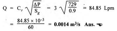
Hydraulics and Pneumatics: Unit II: Hydraulic Actuators and Control Components : Tag: : Hydraulic Actuators and Control Components - Hydraulics and Pneumatics - some illustrative numerical problems
Related Topics
Related Subjects

Hydraulics and Pneumatics
ME3492 4th semester Mechanical Dept | 2021 Regulation | 4th Semester Mechanical Dept 2021 Regulation