Manufacturing Processes: Solved Anna University Question Papers
Solved Anna University Question Papers (Reg 2013 / May 2017)
Manufacturing Processes
Solved Anna University Question Papers: Question Papers 2017 - Manufacturing Processes
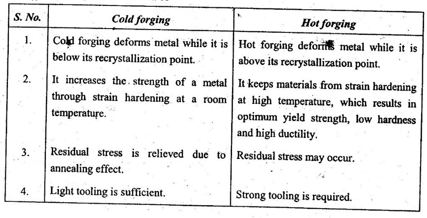
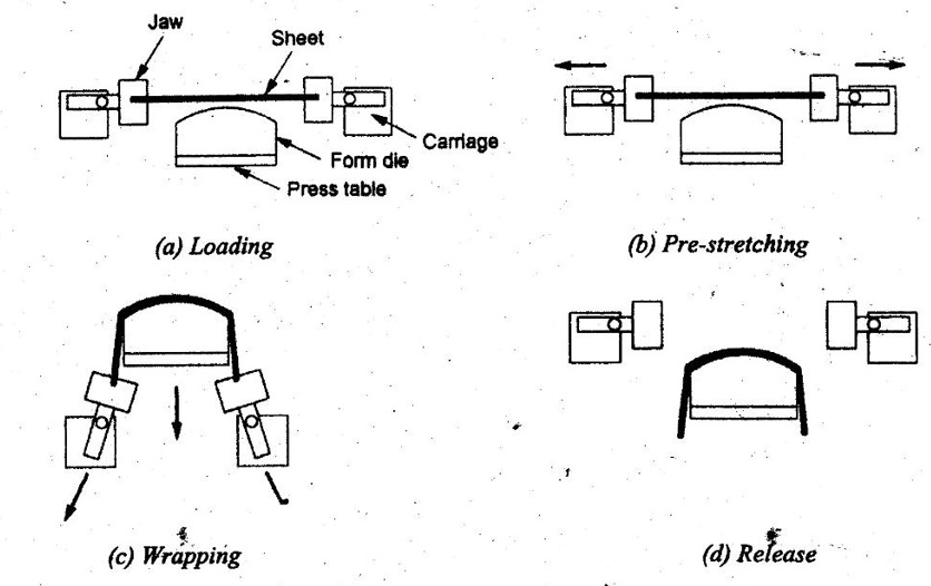
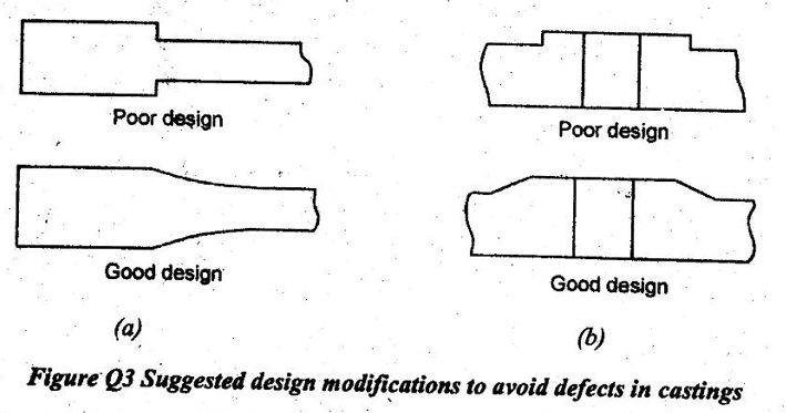
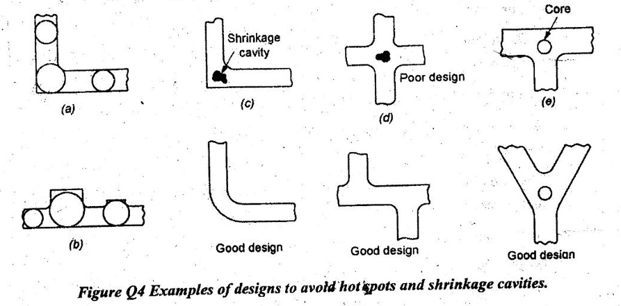
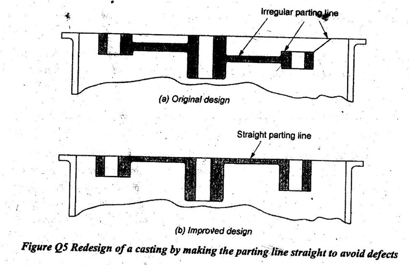
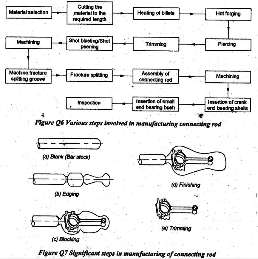
B.E./B.TECH. DEGREE EXAMINATION - April/May 2017 Third Semester Mechanical Engineering ME 6302-MANUFACTURING TECHNOLOGY-I (Common to Industrial Engineering and Industrial Engineering and Management) and Mechanical and Automation Engineering) Time: Three hours Maximum: 100 Marks (Regulation 2013) Answer ALL questions Part A - (10 x 2 = 20 Marks) 1. What is meant by permanent mould casting? Gravity die casting is also called Permanent Mould Casting. The mould is generally made of two halves. They are hinged at one end. There is a provision for clamping them together at the other end. A permanent mould is necessary for producing large number of casting of similar shape. 2. What is the cause of the casting defect called "Hot tear": Hot tear is the crack in the casting caused by high residual stresses. The following are the causes of hot tear: 1. Lack of collapsibility in core and mould. 2. Faulty design. 3. Hard ramming of mould. 3. Sketch an oxidizing flame in Oxy acetylene gas welding. 4. What are the two types of plasma arc welding? 1. Non-transfer type, and 2. Transferred type. 5. How can you reduce the “Roll force” in a rolling process? Rolling forces can be reduced by the following ways: a) Reducing friction by applying lubrication b) Using smaller diameter rolls to reduce the contact area c) Taking smaller reductions per pass (also to reduce the contact area = L) d) Rolling at elevated temperatures to lower the strength of the material e) Applying longitudinal tension to the strip during rolling-back tension on the pay-off reel or front tension on the take-up reel f) Reducing the width of the strip. 6. Differentiate between hot and cold forging. 7. What are the two most common shearing operations? 1. Punching 2. Blanking. 8. What is meant by spring back in sheet metal work? The tendency of the metal that tries to resume its original position causing a decrease in bend angle is known as springback. The springback varies from 0.5° to 5° for steel. Greater springback is caused by a larger bend radius. 9. Define Thermo forming process. It is a process in which a heated plastic sheet is changed to a desired shape by causing it to flow against the mould surface by reducing the air pressure between one side of the sheet and mould surface. 10. Mention any two applications of Blow moulding process? 1. It is used in making plastic bottles and toys. 2. The hollow containers are produced by this process. 3. The multi-layer blow moulding is used in cosmetics and pharmaceutical industries. Part B - (5 × 13 = 65 Marks) 11. (a) With neat sketches, explain the sand casting process. Refer chapter 1.2 in Page 1.1 and Pàge 1.54. Or (b) With a neat sketch, explain the principle of the Investment casting process. Refer chapter 1.14.2 in Page 1.75. 12. (a) Explain the principle and equipment of Gas tungsten arc welding process with neat sketches. Refer chapter 2.6 in Page 2.1. Or (b) (i) Sketch and name the various component of the Thermit welding process. Refer chapter 2.12 in Page 2.50. (ii) Explain any two important defects in welding process. Refer chapter 2.21 in Page 2.80. 13. (a) Sketch and explain the various types of Rolling mill arrangements used in a rolling process. Refer chapter 3.11.1-3.11.7 in Page 3.42-3.44. Or (b) Sketch and explain the differences between Impression die forging and Precision forging (near net shape forging) operation. Refer chapter 3.3.4 in Page 3.8 for impression die forging and chapter 3.3.13 in Page 3.16 for precision forging. 14. (a) With neat sketches explain the sequence of the Stretch forming process. Stretch forming process is carried out in four stages as mentioned below. 1. Loading the sheet blank 2. Pre-stretching 3. Wrapping 4. Release. (i) Loading: Both ends of the sheet blank are inserted in gripper jaws to mount on swing- arm. (ii) Pre-Stretching: The grips are moved away from each other stressing the blank without touching the form block up to 2% elongation. It means, the part is stretched to its yield point. (iii) Wrapping: The part is wrapped around the form die while the stretch force or applied stress is not reduced or varied. The ramming punch is moved towards to build the required contour pressure to form the concave contour. So, the blank is wrapped around the form block. The gripping jaws are moved horizontally and vertically in well-defined manner during the downward motion of the counter pressing punch to prevent tearing of the sheet metal blank in over-stressed regions. (iv) Release: After the wrapping is over, the stretch force is released and the gripper jaws áre opened to eject the formed shape objects. Figure Q2 Sequence in stretch forming process Or (b) With a neat sketch explain the explosive forming process. Refer chapter 4.14.5 in Page 4.49. 15. (a) Explain the Rotational moulding process used in manufacturing plastics, with a neat sketch. Refer chapter 5.3.6 in Page 5.22. Or (b) Explain the Compression moulding process with a neat sketch. Refer chapter 5.4.1 in Page 5.30. Part C (1 × 15 = 15 Marks) 16. (a) Explain the design considerations to be followed when designing à part for the casting process. The following design considerations to be followed when designing a part for the casting process: 1. The part should be designed so that the shape is cast easily. 2. A casting process and material should be selected suitable for the part, size, mechanical properties, etc. 3. The gates are located and designed to allow uniform feeding of the mould cavity with molten metal. 4. Appropriate runner geometry should be selected for the system. 5. Mould features such as sprue, screens and risers should be located, as appropriate. 6. Proper controls and good practices should be in place. 7. Corners, angles and section thickness should be avoided using sharp corners and angles because they may cause cracking and tearing during solidification. These corners, angle and section thickness can be avoided by using fillets with radii ranging from 3 to 25 mm. 8. Sections changes in castings should be blended smoothly into each other. Location of the largest circle that can be inscribed in a particular region is critical so far as shrinkage cavities are concerned shown in Figure Q4 (a) and Figure Q4 (b) because the cooling rate in regions with large circles is lower, they are called hot spots. These regions can develop shrinkage cavities and porosity shown in Figure Q4 (a) and Figure Q4 (b). 9. Cavities at hot spots can be eliminated by using small cores shown un Figure Q4 (e). It is important to maintain (as much as possible) uniform cross sections and wall thicknesses throughout the casting to avoid or minimize shrinkage cavities. Metal chills in the mould can eliminate or minimize hot spots. 10. Flat areas: Large flat areas (plain surfaces) should be avoided since they may warp during cooling because of temperature gradients or they develop poor surface finish because of uneven flow of metal during pouring. this can be eliminated by breaking up flat surfaces with staggered ribs. 11. Shrinkage: Pattern dimensions also should allow for shrinkage of the metal during solidification and cooling. 12. Draft: A small draft typically is provided in sand mould pattern to enable the removal of the pattern without damaging the mould. Drafts generally range from 5 to 15 mm/m. Depending on the quality of the pattern, draft anglès usually range from 0.5° to 2o. 13. Dimensional tolerances: Tolerances should be as wide as possible within the limits of good part performance. Otherwise, the cost of the casting increases. In commercial practices, tolerances are usually in the range of ± 0.8 mm for small castings. For large castings, tolerances may be as much as ± 6 mm. 14. Lettering and markings: It is common practice to include some form of part identification in castings. These features can be sunk into the casting or protrude from the surface. 15. Machining and finishing operations: These operations should be taken into consideration. The parting line is between cope and drag. Some of the considerations in designing parting line are as follows: 1. A part should be oriented in a mould so that the large portion of the casting is relatively low and the height of the casting is minimized. 2. The parting line is line or plane separating the upper (cope) and lower (drag) halves of mould. In general, the parting line should be along a flat plane rather than be contoured. 3. The parting line should be placed as low as possible relative to the casting for less dense metal (such as aluminum alloys) and located at around mid-height for denser metals (such as steels). The gates are connections between runners and part cavity. Some of the considerations in designing gating systems are as follows: 1. Multiple gates often are preferable and they are necessary for large parts. 2. Gates should feed into thick sections of castings. 3. A fillet should be used where a gate meets a casting to produce less turbulence than abrupt junctions. 4. The gate closest to the sprue should be placed sufficiently far away so that the gate can be easily removed. 5. The minimum gate length should be three to five times the gate diameter depending on the metal being cast. 6. Curved gates should be avoided but when necessary a straight section in the gate should be located immediately adjacent to the casting. 7. The runner is a horizontal distribution channel that accepts the molten metal from the sprue and it delivers it to the gates. 8. One runner is used for simple parts but-two runner systems can be specified for more complicated castings. 9. The runners are used to trap dross and keep it from entering the gates and the mould cavity. 10. Commonly, dross traps are placed at the ends of the runners and the runner projects above the gates to ensure that the metal in the gates is trapped below the surface. Or (b) Sketch and explain the sequences of steps in manufacturing a connecting rod using the forging process. (13) The suitable material to manufacture a connecting rod is selected. Then it is cut to the required length called billets. Next, billets are heated in the furnace to the required temperature to carry out the forging process. Successively, piercing and trimming process are performed to make holes and shaping the edges. Then shot blasting or shot peening process is carried to make the surface clean. After that, machining process is performed in several stages to make a connecting rod. During machining, machining of top surface, grinding the side faces, drilling the piston end, broaching of crank and piston rod, drilling bolt hole, drilling of hole and machining of bolt head seat are carried out one after the other. Next, machining fracture splitting groove followed by fracture splitting is done. Then, parts are assembled to make the connecting rod. After the assembling process over, again machining processes such as grinding the side faces, final drilling of crank and piston and milling of bearing positioning groove are performed. Next, the crank end is inserted into the bearing shells and the small end is inserted into the bearing bush. Finally, the connecting rod is inspected to ensure both quality and fitness for the use in practical applicaions.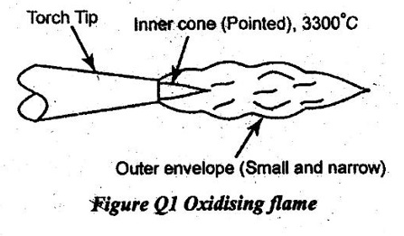
Manufacturing Processes: Solved Anna University Question Papers : Tag: : Manufacturing Processes - Solved Anna University Question Papers (Reg 2013 / May 2017)
Related Topics
Related Subjects
Manufacturing Processes
ME3393 3rd semester Mechanical Dept | 2021 Regulation | 3rd Semester Mechanical Dept 2021 Regulation