Manufacturing Technology: Unit III: Reciprocating Machine Tools
Slotting machines
Reciprocating Machine Tools - Manufacturing Technology
Slotting machine is simply called a slotter. Slotter is a reciprocating type machine tool.
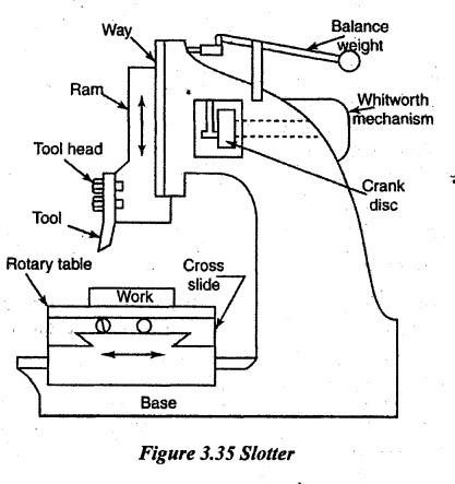
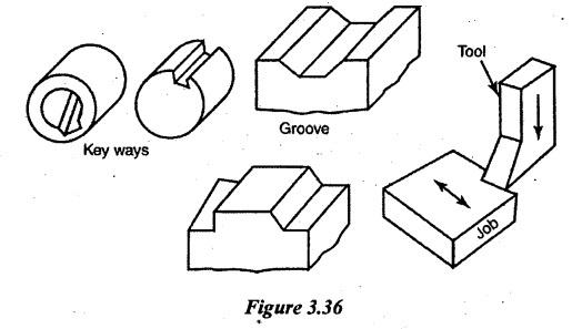
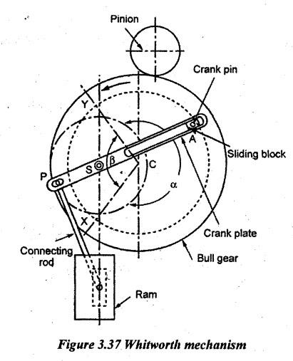
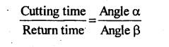
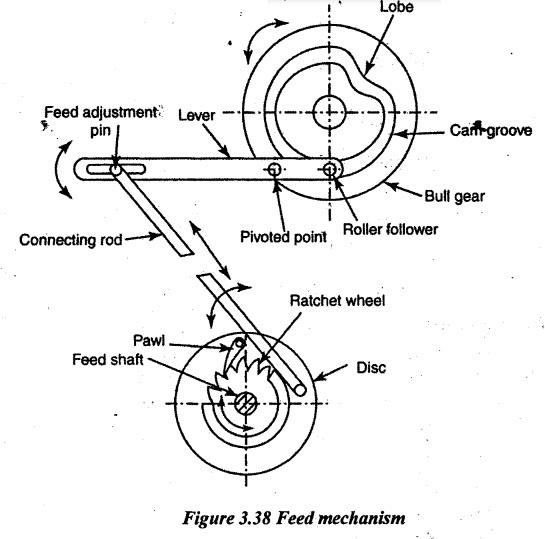
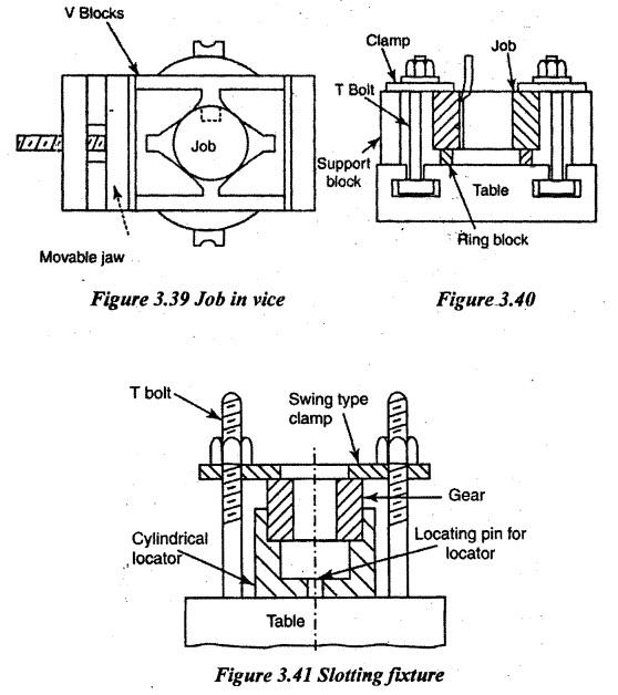
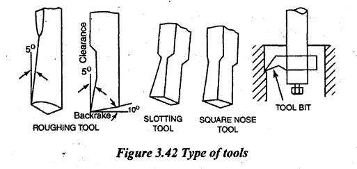
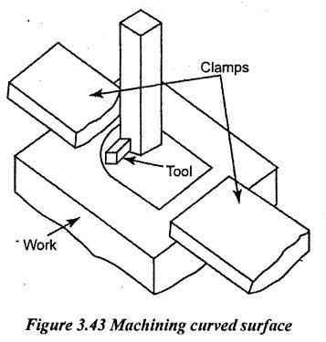
SLOTTING MACHINES Slotting machine is simply called a slotter. Slotter is a reciprocating type machine tool. In this machine, the ram reciprocates vertically. The tool held in the ram cuts during downward stroke only. The major difference between a slotter and a shaper is that the ram holding the tool moves in a vertical axis in a slotter and in a horizontal axis in a shaper. There are three types of slotting machines described below: a) Puncher slotting machine: The puncher slotter is a heavy, rigid machine designed for removal of large amount of metal from large forgings or castings. The length of stroke of a puncher slotter is quite large. In one minute, it removes 1.5 kg to 2.5 kg of material. This type of slotting machine is mainly used in slotting locomotive crank webs from rectangular shapes to exact size in short period of time. (b) General production slotter: This type of slotting machine is mainly used for general purpose production work. It is divided into two categories as follows: (i) First type is having solid body construction. (ii) Second type is having arrangements to tilt the body of the machine about 10° forward and backward for machining accurate internal and external tapers. (c) Precision tool room slotter: A considerable amount of tool room work is carried out on standard production slotter but the amount of accuracy cannot be guaranteed. The slotter frame may be of tilting type with slotted link type of ram drive. This type of slotter can be operated at high speeds. It is mainly used to take light cuts to produce accurate finish. In heavy machines, all table and hand control are conveniently integrated together to perform profiling operation where two feeds should be simultaneously used. The size of a slotter is expressed in terms of maximum length of stroke of the ram in mm. The size of a general purpose or precision slotter ranges from 80 mm to 900 mm. To specify a slotter, the following specifications used are as follows: 1. The maximum stroke length 2. Diameter of rotary table 3. Maximum travel of saddle and cross slide 4. Type of drive used 5. Power rating of motor 6. Net weight of machine 7. Number and amount of feeds, and 8. Floor area required. The parts of slotter are explained below. 1. Base: It is a heavy cast iron construction. It supports the column and the saddle. It has horizontal guide ways on its top. These guide ways are perpendicular to the column.. 2. Column: It is cast integral with base. It houses driving mechanism of ram and feeding mechanism. The top vertical from face has guide ways. The ram slides vertically in it. 3. Saddle It moves on the guide ways provided on the base. It moves either towards or away from the column. It is for longitudinal feed. The top face of saddle has guide ways. These guide ways are perpendicular to the guide ways on the base. A cross slide moves on this guide ways. It moves parallel to the face of the column. It is for cross feed. 4. Rotary table: The rotary table is a circular table. It is mounted on the top of the cross slide. It can be rotated about a vertical axis. It has T-slots on the top. The T-slots are for holding the work. The table bottom is graduated in degrees. 5. Ram and tool head: Ram is a reciprocating member. It slides vertically on the guide ways of the column. It has tool head at its bottom end. The ram has a slot at the back surface. It is for changing the position of ram. The tool is set in the tool holder. The job is held in a vice or clamped directly on the table. The tool is held in the tool post. The ram holding the tool reciprocates vertically. The ram gets power from the driving mechanism. The tool cuts the material in the forward stroke. The return stroke is idle. The feed and depth of cut are given by moving the table. The depth of cut is given by longitudinal movement of the table. The feed is given by cross movement or rotary movement of the table. In slotter, down stroke is the cutting stroke. The return stroke is idle. To reduce the idle return time, quick return mechanism is used. The following quick return mechanisms are used in slotter. 1. Whitworth quick return mechanism 2. Variable speed reversible electric motor drive 3. Hydraulic drive. 1. Whitworth Quick Return Mechanism The mechanism consists of a pinion, bull gear and a crank plate as shown in Figure 3.37. An electric motor drives the pinion. The pinion rotates the bull gear. The bull gear has a crank pin. A sliding block is fitted freely over the crank pin. It also slides in the slot of a crank plate. This crank plate is pivoted eccentrically on a pin 'S'. This pin is fixed to the body of the machine. The crank plate is connected to the ram by a connecting rod through the pins P and A. The crank pin rotates about the center of bull gear 'C'. At the same time, the sliding block (fitted with the crank pin) slides along the slot of the crank plate. This makes the crank plate to rotate about its center 'S'. The crank pin P will also rotate about the center 'S'. Its rotary motion is converted into reciprocating motion of ram by the connecting rod. When the pin A is at X, the ram is at its starting position of forward stroke. When the bull gear rotates in anticlockwise direction, the pin moves through the angle a and reaches the point Y. It is the end position of cutting stroke. When the bull gear rotates further, from Y to X, it makes angle of ß. It is the return stroke. The angle ẞ is smaller than angle a. The speed of bull gear is uniform. So, the time taken for the return stroke is less than cutting stroke. In slotter, the feed is given by the table. It is given at the beginning of cutting stroke. The slotter has three types of feed movement. 1. Longitudinal feed: It is given by moving the table (saddle) either towards or away from the column. 2. Cross feed: It is given by moving the table (cross slide) parallel to the face of column. 3. Circular feed: It is given by rotating the table about a vertical axis. All feed movement can be given either by hand or power. Hand feed is given by rotating the respective feed screw through hand wheels. 1. Automatic Feed Mechanism The bull gear has a cam groove on its face. A roller follower slides in this groove. The roller is attached to a lever. This lever has a slot on the other end. The lever is pivoted at the middle with the body. A feed adjustment pin is fitted in the slot of the lever. One end of connecting rod is connected to a disc. The disc rotates freely on the feed shaft. The disc carries a pawl. The roller follows the groove when the bull gear is rotated. When the cam lobe passes the roller, the lever has oscillation. This oscillation is transmitted to the disc through connecting rod. Now, the pawl moves in both directions. When the pawl moves in anticlockwise direction, it rotates the ratchet wheel. The feed shaft keyed to the ratchet wheel also rotates. The feed shaft may be engaged to the longitudinal, cross or rotary feed screws. The amount of feed is adjusted by adjusting the position of the feed adjustment pin. The work is held on a slotter table by a vice, using 'T' bolts and clamps or by special fixtures. The work is placed above the parallel or packing pieces. This permits the over travel of tool. Figure 3.39 illustrates the method of holding a work (gear) on the slotter table for cutting internal keyway. The gear is placed on a ring block. The axis of gear is aligned with the axis of the rotary table. It is clamped by using ‘T' bolts and clamps. Cylindrical jobs can be held in a vice by using 'V' block as shown in the Figure 3.40. The vice is clamped in the table. Special fixtures can be used as shown in Figure 3.41. In this, a gear blank is located by a cylindrical locator. The cylindrical locator is located by a pin at the center of table. Hence, axis of gear is located at the center of table. The clamping plate and T bolts are used to clamp the work. The tool in a slotter removes metal during its vertical cutting stroke. So, the cutting pressure acts along the length of the tool. Therefore, it has thick cross section. The tool angles are given with respect to vertical plane. Usually, the tools are forged type. Bit tools, held in heavy tool holders, are also used. The tools are provided with top rake, front clearance and side clearance. No side rake is given. The nose of tool projects slightly beyond the shank. This is to give clearance for cutting. Figure 3.42 illustrates the different Slotter tools: Keyway cutting tools are thinner at the cutting edge. Round nose tools are used for machining contoured surface. Square nose tools are for machining flat surfaces. The different operations done in a slotter are 1. Machining flat surface. 2. Machining grooves, slots, keyways. 3. Machining cylindrical surface. 4. Machining irregular surface. 1. Machining Flat Surface The work is clamped on the table or vice. The work is set parallel to the column. Rotary movement of table is locked. Depth of cut is given by moving the saddle. Feed is given by moving cross slide. In this method, internal and external flat surfaces can be machined. 2. Machining Keyway The workpiece may be fixed by using vice or on table as shown in Figure 3.43. For cylindrical workpieces, the center of job must be aligned with center of table. The length and position of stroke is adjusted. The slot is finished giving rough and finish cuts. 3. Machining Cylindrical Surface The workpiece may be clamped in a vice or in the table or in a fixture. The center of job must be aligned with the center of table. The rotary table is set at centre. Then only the cutting takes place in radial direction. This is done by adjusting the saddle and cross slide. Then the saddle and cross slide are locked. Work is finished by giving circular feed. 4. Machining Irregular Profiles Irregular profiles are machined by combining longitudinal feed, cross feed and circular feed. The calculations of speed, feed and depth of cut are similar to a shaping machine. 1. Cutting speed: The cutting speed of a slotter is defined by the rate with which the metal is removed during downward cutting stroke and it is expressed in meters per minute. 2. Feed: It is the movement of the work per double stroke expressed in mm. 3. Depth of cut: It is the perpendicular distance measured between machined surface and unmachined surface expressed in mm. Recommended tolerances for dimensions and surfaces produced on planers, shapers, and slotters. (Source: Design for Manufacturability Handbook by James G Bralla, 2nd Ed.) Dimensional factors and tolerances: The major dimensional variations might occur from human factors. These are (i) Design and condition of the part (ii) Clamping method It is necessary to have a square and flat clamping surface of the workpiece. A distorted piece in clamping will spring back after machining and will not have a true surface. It is very crucial in planer machined parts when cutting forces are really high. Hence, the solidity of clamps, supports and stops is relatively important. Further, dimensional error might arise due to movement of the workpiece and deflection of the part as a result of cutting forces. Due to release of internal stresses in the material during machining (especially flat pieces), warp age also might occur. In slotting operations or in the shaping of internal surfaces, when there is substantial overhang of the tool or tool holder, the aspect of rigidity comes into picture. In addition, the factors which will improve accuracy in tooling are slower cutting speeds, lighter cuts with finer feeds and the use of lubricants and facilitate smooth finish are sharp tools, correctly ground and fine feeds.1. TYPES OF SLOTTING MACHINES
2. SIZE OF SLOTTING MACHINES
3. PRINCIPAL PARTS OF A SLOTTING MACHINE
4. METHOD OF OPERATION
5. DRIVING MECHANISM IN SLOTTING MACHINES
6. FEED MECHANISM
7. WORK HOLDING DEVICES IN SLOTTING MACHINES
8. SLOTTING MACHINE TOOLS
9. OPERATIONS PERFORMED ON SLOTTING MACHINES
10. CUTTING SPEED, FEED AND DEPTH OF CUT FOR SLOTTING MACHINES
11. SURFACE ROUGHNESS OBTAINABLE IN SHAPING, PLANING AND SLOTTING MACHINES

Manufacturing Technology: Unit III: Reciprocating Machine Tools : Tag: : Reciprocating Machine Tools - Manufacturing Technology - Slotting machines
Related Topics
Related Subjects

Manufacturing Technology
ME3493 4th semester Mechanical Dept | 2021 Regulation | 4th Semester Mechanical Dept 2021 Regulation