Manufacturing Technology: Unit II: Turning Machines
single spindle automatic lathes
Turning Machines - Manufacturing Technology
A single spindle automatic lathe is a modified form of turret lathe. These machines have an addition to a 6-station or 8-station turret, a maximum of 4 cross slides.
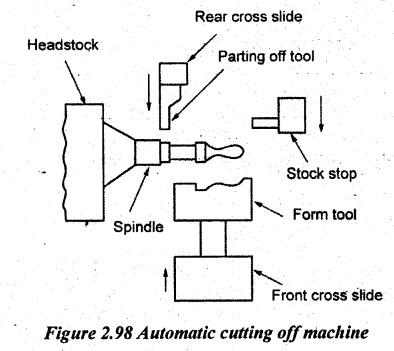
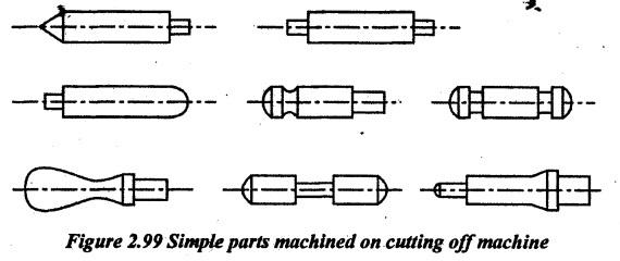
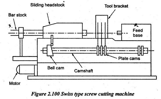
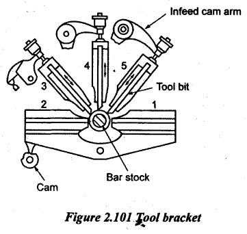
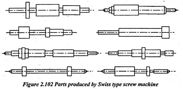
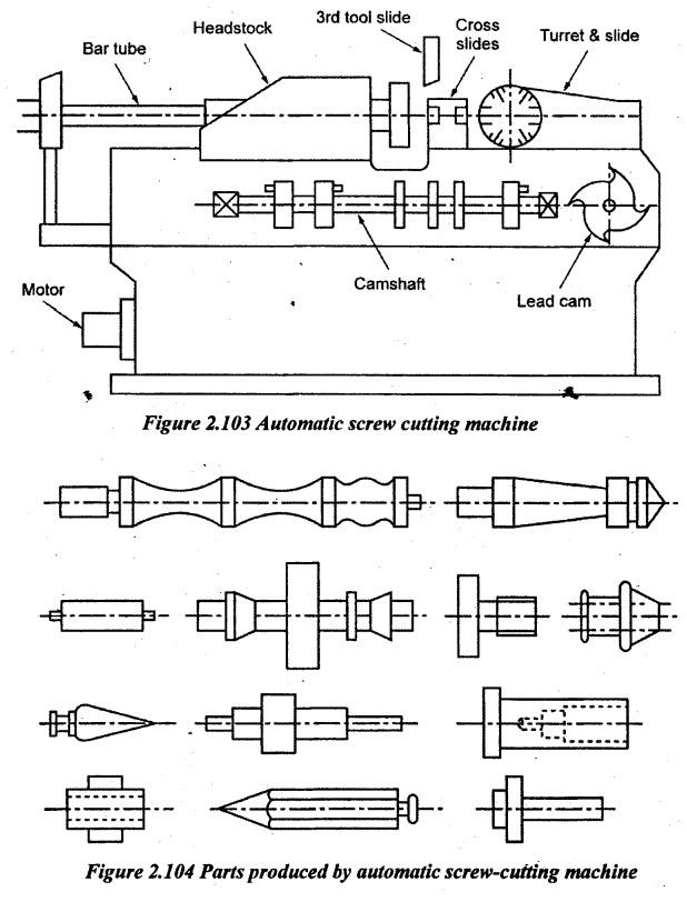
SINGLE SPINDLE AUTOMATIC LATHES A single spindle automatic lathe is a modified form of turret lathe. These machines have an addition to a 6-station or 8-station turret, a maximum of 4 cross slides. These cross slides are operated by disc cams. The cams are mounted on a shaft which draws power from the main spindle through a set of gears called cyclic time change gears. Turret operation is also synchronized with the cross slide operation and is driven by another cam called main cam. The tools used on the cross slides are usually form tools and are plunged into the workpiece at the desired feed rate. The tools used in the turret may be turning tool, drilling tools etc. It is common to use more than one tool on a turret station. External threading is usually carried out by a thread chasing attachment. Internal threads are made using taps. In addition, milling of slots, flats, grooves, cross-drilling etc. can be carried out. It can be performed in an automatic lathe with the help of special attachments. It is one of the outstanding features of automatic lathe. The reduction in number of set ups and total machining time enables the parts to be produced at an economical cost in an automatic lathe. Because of their application to produce screws at low cost, these are called screw cutting machines. Figure 2.97 shows the single spindle automatic lathe. The lathe has a geared headstock. The spindle of the headstock has one slow speed and one fast speed. The spindle speed is changed by the trip dogs on the drum A. At the end of bed, a square turret is provided. The travel of the turret slide is controlled by the adjustable cam drum C. The turret is indexed to the next position at the end of each stroke. Two cross slides are situated between headstock and turret. One cross slide is at the front side and the other at the rear side. The cross slides have independent movements. The travel of cross slides are independently controlled by a cams B. Overlapping of operations by the tool in the turret and the tools in the cross slide can be done. The correct feed for each machining operation can automatically be selected by the feed selector pins on the drum D. The following types of the single spindle automatic lathe are mostly used. 1. Automatic cutting off machine, 2. Automatic screw cutting machine 3. Swiss type automatic screw machine. These machines are simple in design and they are used for producing large quantities of parts of smaller diameter and shorter length. The components of simple shapes are produced in this machine. The principle of an automatic cutting off machine is shown in Figure 2.98. In this machine, the headstock with the spindle is mounted on the bed. Two cross-slides are located on the bed, one at the front end of the spindle and other at the rear end of the spindle. Front cross slide tools are used to perform the main operations such as forming. Rear cross slide tools can perform the operations such as facing, chamfering, cutting off etc. Cams. on a camshaft are actuating the working movements of the cross-slides through a system of levers. To cut threads and machining holes, special attachments are used. It is also provided with a controlling movement of the turret. This provision helps the tools to feed into the work at desired speeds. It was accomplished by means of a cylindrical cam or drum cam located beneath turret. It also consists of a mechanism for clamping the work in the collet. The bar stock is held in a collet chuck. A bar stop held on a slide is automatically advanced in line with the spindle axis at the end of each cycle. The stock is fed out of the collet by a bar feeding mechanism up to the stop. Bar feeding is done by a cam mechanism. In some machines, an end-working slide is available. This slide travels along the spindle axis. Using this slide, drilling and reaming operations can be carried out. Various simple parts machined in this machine are shown in Figure 2.99. The size of parts varies from 3mm to 20mm diameter. Salient features of automatic cutting off machine: (a) It is more compact in size. So, it allows an operator to operate more than on units simultaneously. (b) It has good adaptability which improves the productivity. (c) There is no need to align the screws. (d) It is widely applicable in screws of various types, length and head shape. (e) It has a unique testing loop which allows for the minimal running time. This type of automatic lathe is suitable for small, long and slender parts such as parts of wristwatches. There is a distinct difference between conventional automatic lathes and Swiss type automatic lathes. In the latter, the work is fed against the tool. The headstock carrying the bar stock moves back and forth for providing the feed movement in the longitudinal direction. Hence, this type of automatic lathe is also called a sliding head automatic lathe. This machine is used for producing long accurate parts of small diameter (2 to 25 mm). In this, the parts can be machined to an accuracy of 0.005 mm to 0.0125 mm. There may be five cross slides in the case of automatic lathe. However, the productivity- wise, the conventional automatic lathes are superior for short workpieces. The advantage of a sliding head automatic lathe is that the long slender workpieces can be machined with a very good surface finish, accuracy and concentricity in sliding head automatic lathes. Further, Swiss type automatic lathes are capable of completely machining certain types of parts which may require second and third operations in conventional automatic machines. Figure 2.100 shows a Swiss type screw cutting machine. It consists of four major parts. 1. The sliding headstock through which the bar stock is passed and gripped by a carbide-lined guide bush. 2. The camshaft which controls the bar stock and cutting tool movements. 3. The tool bracket which supports five tool slides and a bush for stock. 4. Auxiliary attachments for performing various operations such as knurling, drilling, tapping, screwing, slotting, recessing etc. The description of various parts is given below. 1. Sliding headstock: This headstock has a collet. The bar stock is held in the collet. The headstock slides along the guide ways of the bed. A bell cam connected to the camshaft controls this sliding motion. 2. Tool bracket: The tool bracket is mounted on the bed way near the headstock. The tool bracket supports 4 or 5 tool slides. It also has a bush for supporting and guiding the bar stock. Two slides are horizontally positioned i.e. one at the front and the other at the rear. The other slides are arranged above these slides. All slides can move back and forth. These slides are independently actuated by sets of rocker arms and plate cams. Plate cams are fitted to the camshaft. Figure 2.101 shows the schematic of tool bracket. 3. Feed base: The feed base is mounted at the right-hand side of the headstock. It can move along the bed. Using this attachment, operations such as drilling, boring, thread cutting etc., are done. The movement of the feed base is controlled by the plate cam fitted to the camshaft. 4. Camshaft: The camshaft is mounted at the front of the machine. It has a bell cam at the left end which controls the sliding movement of the headstock. Plate cams fitted at the centre of the shaft controls the movement of the tool slides. A plate cam at the right end of the camshaft controls the movement of the feed base. The parts produced in this machine are shown in Figure 2.102. Working principle: The bar stock is held in the rotating spindle by a collet chuck. Headstock slides along the bed ways with the rotating bar stock. This headstock movement gives a longitudinal feed to the work. All tools in the tool slides remove material from the workpiece at the same time. The tool in the feed base attachment may also do operations such as drilling. After the workpiece is machined, the headstock slides back to the original position. One revolution of the camshaft produces one component. Most of the turning and forming operations are done by the tools held on the (horizontal) front and rear tool slides. The vertical tool slides are mainly used for undercutting, chamfering, knurling and cutting off. Advantages of Swiss type screw machine: 1. It is used to manufacture precision turning of small parts. 2. It has five tool slides. 3. A wide range of speeds is available. 4. It is rigid in construction. 5. Micrometer tool setting is possible. 6. Interchangeability of cams is possible. 7. Simple design of cams is enough. 8. Tolerance of 0.005 to 0.0125 mm is obtained. 9. Numerous working stations are available. These machines are essentially automatic bar type turret lathes. They are widely used for the production of all sorts of small turned parts. It mainly consists of a cross slide and turret. Two cross slides, one front cross slide and another rear cross slide are provided for cross feeding tools. An additional vertical slide is also employed in this machine. This third slide is installed above the work spindle. The line diagram of this machine is shown in Figure 2.103. The turret slide is placed at the right end of the bed. It carries the turret having six tool holes. The various tools used in the machine are mounted on the turret in a vertical plane in line with the spindle. In this machine, the headstock is stationary. It houses the spindle which rotates in either direction. The bar stock is held in a chuck. It is advanced by a feed finger after each piece is finished and cut off. A camshaft is mounted at the front of the machine. It carries three plate cams. These plate cams control the travel of cross slides. The turret head rotates about a horizontal axis. The turret slide travel is controlled by a lead cam. The lead cam gives a slow forward and fast return movement to the turret slide. The discs cams are used to control the cross slide. All operations such as turning, drilling, boring, threading, reaming, spot facing, knurling can be performed on the machine. Special attachments are also available to perform slotting work, milling flats, cross-drilling etc. In this machine, any type of bar stock such as round, square, hexagonal can be machined. These machines are made in several sizes for bar work from 12 mm to 60 mm diameter. The parts produced in an automatic screw-cutting machine are shown in Figure 2.104. Applications: It is used for producing small jobs, screws, stepped pins, taper pins, bolts etc.
1. Automatic Cutting Off Machine
2. Swiss Type Automatic Lathes (Sliding Head Automatic Lathes)
3. Single Spindle Automatic Screw Cutting Machine
Manufacturing Technology: Unit II: Turning Machines : Tag: : Turning Machines - Manufacturing Technology - single spindle automatic lathes
Related Topics
Related Subjects

Manufacturing Technology
ME3493 4th semester Mechanical Dept | 2021 Regulation | 4th Semester Mechanical Dept 2021 Regulation