Theory of Machines: Unit III: Friction in Machine Elements
single plate (or disc) clutch
Friction in Machine Elements - Theory of Machines
This type of clutch is mostly used in motor vehicles.
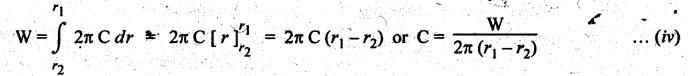
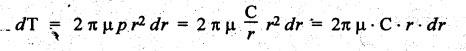
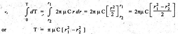
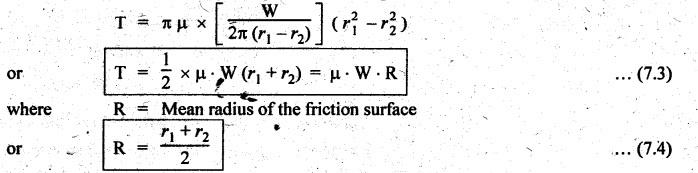
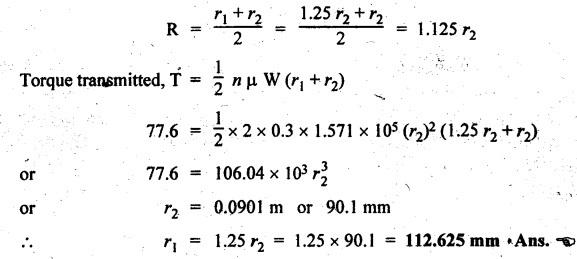
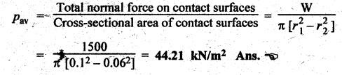
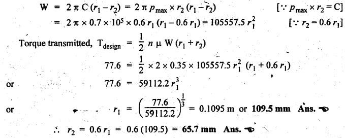
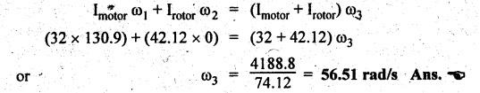
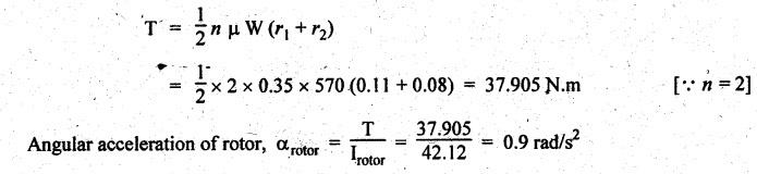
SINGLE PLATE (OR DISC) CLUTCH This type of clutch is mostly used in motor vehicles. It consists of one clutch plate, clutch shaft, clutch spring, pressure plate, friction lining and bearing. The flywheel is mounted on the engine crankshaft and rotates with it. The pressure plate is bolted to the flywheel through clutch springs. The friction linings are on both sides of the clutch plate. Fig.7.3 shows the arrangement of single plate clutch. Operation: When the clutch is engaged, the clutch plate is gripped between the flywheel and the pressure plates. Due to friction, the clutch plate and shaft revolves. When the clutch pedal is pressed, the pressure plate moves back against the force of the springs, and the clutch plate becomes free between the flywheel and the pressure plate. Thus the flywheel remains rotating as long as the engine is running and the clutch shaft speed reduces slowly and finally it stops rotating. Consider two friction surfaces that are held together by an axial thrust W, as shown in Fig.7.4. Let T = Torque transmitted by the clutch, p = Intensity of axial pressure acting on contact surfaces; r1 = External radius of friction surface, r2 = Internal radius of friction surface, and μ = Coefficient of friction between contacting surfaces. Consider an elementary ring of radius r and thickness dr, as shown in Fig.7.4(b). Area of the elemental ring, dA = 2πr dr Axial load on the ring, dW = Pressure × Area = p × 2πr dr and the frictional force on the ring, dF = μ • dW = μ (p 2πr dr) ⸫ Frictional torque acting on the ring, dT = dF × r The design of friction clutch is done based on any one of the following assumptions: 1. when there is a uniform pressure, and 2. when there is a uniform wear. 1. Considering Uniform Pressure When the pressure is assumed to be uniform over the friction surface, then the intensity of pressure (p) is given by Now the total frictional torque acting on the friction surface or on the clutch is obtained by integrating equation (i) within the limits from r2 to r1. Substituting the value of p from equation (ii), we get 1. Considering Uniform Wear For uniform wear, the intensity of pressure varies inversely with the distance. Therefore, We know that load on the ring, ⸫ Total force acting on the friction surface, We know that the frictional torque acting on the ring, Now the total frictional torque on the friction surface is obtained by integrating the equation (v) within the limits r2 to r1. Substituting the value of C from equation (iv), we get Note 1. In general, total frictional torque acting on the friction surface or on the clutch is given by where n = Number of pairs of friction or contact surfaces. 2. For single disc plate clutch, n = 2. Since both the sides of the disc are in contact. 3. While solving the problem, if the word 'new clutch' is given, then consider as an uniform pressure problem. But if the word 'old clutch' is given, then it is an uniform wear problem. If nothing is stated, then uniform wear should be considered for power transmission by friction through the clutch. 4. Intensity of pressure is maximum at the inner radius (r2) and minimum at the outer radius (r1) of the friction surface. Therefore equation (iii) can be written as pmax × r2 = C or pmin × r1 = C 5. The average pressure (pav) on the friction or contact surface is given by Example 7.1 An automotive single plate clutch consists of two pairs of contacting surfaces. The inner and outer radii of friction plate are 120 mm and 250 mm respectively. The coefficient of friction is 0.25 and the total axial force is 15 kN. Calculate the power transmitting capacity of the clutch plate at 500 rpm using (i) uniform wear theory, and (ii) uniform pressure theory. Given data: n = 2; r1 = 250 mm = 0.25 m; r2 = 120 mm = 0.12 m; W = 15 kN = 15 × 103 N; N = 500 rpm; μ = 0.25. Solution: (i) Using uniform wear theory: Torque transmitted on clutch is given by (ii) Using uniform pressure theory: Torque transmitted on clutch is given by Example 7.2 A single plate friction clutch, with both sides of the plate being effective, is used to transmit power at 1440 rpm. It has outer and inner radii 80 mm and 60 mm respectively. The maximum intensity of pressure is limited to 10 x 10 N/m2. If the coefficient of friction is 0.3, determine: (i) total pressure exerted on the plate, and (ii) power transmitted. Given data: n = 2; N = 1440 rpm; r1 = 80 mm 0.08 m; r2 = 60 mm = 0.06 m; Pmax = 10 × 104 N/m2; μ = 0.3 Solution: (i) Total pressure exerted on the plate: Since the intensity of pressure (p) is maximum at the inner radius (r2), therefore for uniform wear (ii) Power transmitted: Example 7.3 A single plate clutch, effective on both sides, is required to transmit 25 kW at 3200 rpm. Determine the outer and inner radii of frictional surface if the coefficient of friction is 0.3, the ratio of radii is 1.25 and the maximum pressure is not to exceed 0.1 N/mm2. Also determine the axial thrust to be provided by the springs. Assume the theory of uniform wear. [A.U., May/June 2007] Given data: P = 25 kW = 25 × 103 W; N = 3200 rpm; n = 2; pmax = 0.1 N/mm2 = 0.1 × 10⁶ N/m2; μ = 0.3. Solution: (i) Outer and inner diameter of the plate: Since the intensity of pressure is maximum at the inner radius (r2), therefore and the axial thrust transmitted to the frictional surface, and mean radius for uniform wear is given by (ii) Axial force to engage the clutch: We know that the axial force to engage the clutch, Example 7.4 The external and internal radii of a friction plate of a single clutch are 120 mm and 60 mm respectively. The friction surfaces are held together with a total axial thrust of 1500 N. For, uniform wear, find the maximum, minimum and average pressure on the contact surface. Given data: r1 = 120 mm = 0.12 m; r2 = 60 mm = 0.06 m; W = 1500 N. Solution: Maximum pressure: Since the intensity of pressure is maximum at the inner radius (r2), therefore Axial force exerted on the contact surface (W) is given by Minimum pressure: Since the intensity of pressure is minimum at the outer radius (r1), therefore Axial force exerted on the contact surface (W) is given by Average pressure: Example 7.5 A 10 kW engine develops a maximum torque of 100 N.m and is driving a car having a single plate clutch of two active surfaces. Axial pressure is not to exceed 0.85 bar. External diameter of friction plate is 1.25 times internal diameter. Assume uniform wear and coefficient of friction = 0.3. Determine dimensions of friction plate and axial force exerted by the springs. Given data: P = 10kW = 10 × 103 W; T = 100 N.m; n = 2; pmax = 0.85 bar = 0.85 × 10⁵ N/m2; d1 = 1.25 d2 or r1 = 1.25 r2 = 1.25; μ = 0.3 Solution: (i) Dimensions of the friction plate: Assume uniform wear. Since the intensity of pressure is maximum at the inner radius (r2), therefore pmax × r2 = C or C = 0.85 × 10⁵ × r2 N/m and the axial force exerted by the springs, (ii) Axial force exerted on the springs: We know that the axial force exerted on the springs, Example 7.6 A single dry plate clutch transmits 7.5 | 1 at 900 rpm. The axial pressure is limited to 0.07 N/mm2. If the coefficient of friction is 0.25, find (i) mean radius and face width of the friction lining assuming the ratio of the mean radius to the face width as 4 and (ii) outer and inner radii of the clutch plate. Given data: P = 7.5 kW = 7.5 × 10³ W; N = 900 rpm; pmax = 0.07 N/mm2 = 0.07 × 10⁶ N/m2; μ= 0.25; R/b = 4. Solution: (i) Mean radius (R) and face width (b) of the friction lining: Assuming uniform wear, the torque transmitted (ii) Outer and inner (r1 and r2) of the clutch plate: We also know that the width of the clutch plate is equal to the difference of the outer and inner radii. ⸫ b = r1 - r2 On solving (i) and (ii), we get Example 7.7 A car engine develops maximum torque at 15 kW and 2400 rpm. The data provided for the clutch design are the following: (i) Intensity of pressure on the friction surface not to exceed 0.7 bar. (ii) Provision is to be made for the loss of torque to wear as 30% of the engine torque. (iii) Coefficient of friction for the mating lining riveted on both sides of the plate is 0.35. (iv) Inside diameter of the friction plate is 0.6 times the outside diameter. Determine the suitable dimensions of the clutch plate. Given data: P = 15 kW = 15 × 103 W; N = 2400 rpm; pmax = 0.7 bar = 0.7 × 10⁵ N/m2; n = 2; μ = 0.35; d2 = 0.6 d1 or r2 = 0.6 r1 Solution: Maximum torque developed by the engine at 2400 rpm is given by Taking into account the provision to be made for the loss of torque due to wear so that after this loss also the clutch is able to transmit the maximum engine torque, we get The axial force exerted by the springs is given by Example 7.8 A rotor is driven by a co-axial motor through a single plate clutch, both sides of the plate being effective. The external and internal diameters of the plate are respectively 220 mm and 160 mm and the total spring load pressing the plates together is 570 N. The motor armature and shaft has a mass of 800 kg with an effective radius of gyration of 200 mm. The rotor has a mass of 1300 kg with an effective radius of gyration of 180 mm. The coefficient of friction for the clutch is 0.35. The driving motor is brought up to a speed of 1250 rpm when the current is switched off and the clutch suddenly engaged. Determine: (i) The final speed of motor and rotor, (ii) The time to reach this speed, and (iii) The kinetic energy lost during the period of slipping. Given data: d1 = 220 mm or r1 = 110 mm = 0.11 m; d2 = 160 mm or r2 = 0.08 m; W = 570 N; mmotor = 800 kg; kmotor = 200 mm = 0.2 m; mmotor = 1300 kg; kmotor = 180 mm = 0.18 m; μ = 0.35; N1 = 1250 rpm. Solution: (i) Final speed of motor and rotor: Let ω1 = Initial speed of motor armature and shaft, ω2 = Initial speed of rotor = 0, and ω3 = Final speed of motor armature and shaft. We know that the angular momentum before slipping is equal to the angular momentum after slipping. (ii) Time to reach this speed: We know that the torque transmitted by a clutch, Let t = Time taken by rotor to reach the speed of 56.51 rad/s, and αrotor = Angular acceleration of rotor. Assuming a to be uniform, we can write (iii) Kinetic energy lost during the period of slipping: Angular kinetic energy before engagement, Angular kinetic energy after engagement,
1. Torque Transmitted by the Single Plate Clutch


Theory of Machines: Unit III: Friction in Machine Elements : Tag: : Friction in Machine Elements - Theory of Machines - single plate (or disc) clutch
Related Topics
Related Subjects

Theory of Machines
ME3491 4th semester Mechanical Dept | 2021 Regulation | 4th Semester Mechanical Dept 2021 Regulation