Engineering Graphics: Unit IV (a): Sections of Solids
Sections of cylinder
Construction, Steps, Example Problems | Engineering Graphics (EG)
The cylinder is resting on its base on HP. ie., axis is perpendicular to HP. Hence true shape can be seen on top view. Top view to be drawn first.
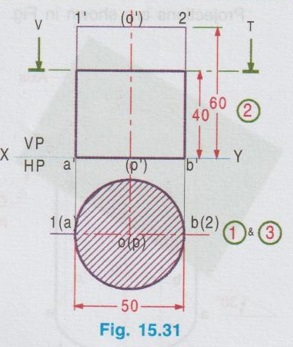
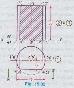
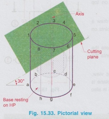
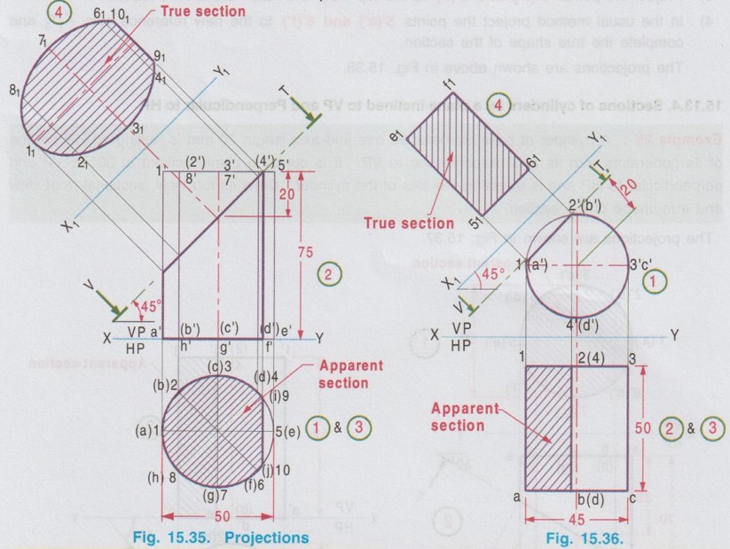
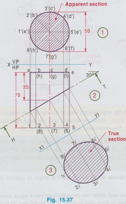
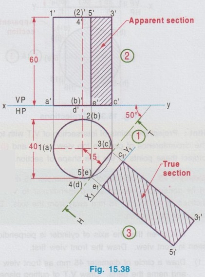
SECTIONS OF CYLINDER Example 21: A cylinder with 50 mm base diameter and 60 mm long axis is resting on its base on HP. It is cut by a section plane parallel to and 40 mm above HP. Draw its front view and sectional top view. The cylinder is resting on its base on HP. ie., axis is perpendicular to HP. Hence true shape can be seen on top view. Top view to be drawn first. Step 1 (Top view): Draw the reference line XY and draw a circle of diameter 50 mm as the top view and name the points on circumference as 1(a) and 2(b). Step 2 (Front view): Project the top view and complete the front view as a rectangle of height 60 mm which represents the length of axis. Name the points as 1', 2', a' and b'. Step 3 (Section) : Draw V.T of cutting plane, in front view, parallel to HP and 40 mm above HP. Since the cutting plane is parallel to HP, the entire top view will be in section which is also the true section. Hatch the circle drawn in top view. Example 22: A cylinder of 45 mm diameter and 60 mm height stands vertically with its base on HP. It is cut by a section plane perpendicular to HP and Parallel to VP, at a distance of 15 mm from the axis. Draw its top view and sectional front view. Step 1 (Top view): Draw a circle of diameter 45 mm as the top view. Name the end points of horizontal diameter as 1(a) and 2(b). (1 and 2 are the points on the circumference of top base whereas a and b are the corresponding points on the circumference of bottom base). Step 2 (Front view): Project the top view and complete the front view as a rectangle of height 60 mm. Mark the points 1', 2', a' and b'. Step 3 (Section): Draw H.T of cutting plane in top view, parallel X to XY and at 15 mm from the axis. Let the points of intersection of H.T with the circumference of circle be 3(c) and 4(d). Project these points to the front view using thicklines and mark the corresponding points as 3', 4', c' and d'. Hatch the area enclosed by the lines joining these points. Since the plane is parallel to VP, the section seen in front view itself is the true shape of the section. Example 23: A cylinder of base diameter 40 mm and height 60 mm rests on its base on HP. It is cut by a plane perpendicular to VP and inclined at 35° to HP and meets the axis at a distance 30 mm from bottom base. Draw front view, sectional top view and true shape of the section. Fig. 15.33 shows the pictorial view of the cylinder, resting on its base on HP, axis perpendicular to HP. Circumference at bottom and top are divided into eight equal parts and named as a, b, ...... h and 1, 2, ....... 8 respectively. Projections are shown in Fig. 15.34. Step 1 (Top view): Draw a circle of diameter 40 mm as the top view. Divide the circumference of circle into eight equal parts. Name the points as a, b, c etc., and 1, 2, 3 ... etc., showing hidden points within the bracket. Step 2 (Front view): Project the top view, by drawing vertical projectors through all the points on the circumference of circle to draw front view and name the points as a', b', c' etc., and 1', 2', 3', etc., Step 3 (Section): Cutting plane is inclined to HP at 35°, Hence draw V.T of cutting plane inclined at 35° to XY, cutting the axis at 30 mm from its bottom base. Assuming the portion of cylinder in front view above cutting plane is removed darken the remaining portion using thick lines. As the cutting plane cross the entire width in front view, the entire area in top view is in section. Hence hatch the top view using thin lines inclined at 45°. Step 4 (True shape): Draw another axis X1Y1, parallel to the cutting plane at any convenient distance. Draw the projectors through all the points on the cutting plane, perpendicular to the cutting plane. Locate the points 11, 21, 31 etc., on the projectors drawn through points of intersection of cutting line with vertical lines drawn through 1, 2, 3 etc., respectively in such a way that the distances of 11, 21, 31 etc., from X1Y1 are equal to the corresponding distances of 1, 2, 3 etc. from XY. Join these points in a sequence by a smooth curve and hatch the area enclosed using thin lines inclined at 45° which gives the true shape of section. Example 24: A cylinder of base diameter 50 mm and 75 mm height rest on its base on HP. It is cut by a plane perpendicular to VP and inclined at 45° to HP. The cutting plane cuts the axis at a point distant 55 mm from the bottom base. Draw its front view, sectional top view and true shape of the section. This is similar to the previous problem. But the V.T of cutting plane does not cut the entire width in front view, and hence the entire top view will not be in section. Hint: Project the points of intersection of V.T with top edge in front view to the top view to intersect the circumference of circle in top view at (i)9 and (j)10. Hatch the topview upto this edge and also project these points to the true shape of section. The projections are shown in Fig. 15.35. Example 25: A cylinder of base diameter 45 mm and axis length 50 mm is resting on HP on one of its generators with its axis perpendicular to VP. It is cut by a plane perpendicular to VP and inclined at 45° to HP, 15 mm away from the axis. Draw the front view, sectional top view and true shape of the section. It is given that the axis of cylinder is perpendicular to VP hence the true shape of cylinder is seen in front view. Draw the front view first. 1) Draw a circle of diameter 45 mm as front view and divide the circumference into 4 equal parts and name the parts. Draw V.T of cutting plane in front view inclined at 45° to XY and 20 mm from axis. Let V.T cuts the circumference of circle in front view at 5'(e') and 6'(f'). Note: To draw V.T at 20 mm away from axis the following procedure may be followed). Draw a line inclined at 45° through the centre of circle. Draw a perpendicular line through the centre, perpendicular to the line drawn earlier and mark a point on it at 20 mm from centre and then draw a line passing through this point inclined at 45° to XY. 2) Project the front view and complete the top view. Name the points accordingly. 3) Project the points 5'(e') and 6'(f') to the top view and hatch the area enclosed. 4) In the usual method project the points 5'(e') and 6'(f') to the new reference axis X1Y1 and complete the true shape of the section. The projections are shown above in Fig. 15.36. 4. Sections of cylinders by a plane inclined to VP and Perpendicular to HP Example 26: A cylinder of base diameter 50 mm and axis length 70 mm is resting on HP on one of its generators with its axis perpendicular to VP. It is cut by a plane inclined at 30° to VP and perpendicular to HP and is bisecting the axis of the cylinder. Draw its top view, sectional front view and true shape of the section. The projections are shown in Fig. 15.37. Example 27: A cylinder of base diameter 40 mm and axis length 60 mm is resting on HP on its base. It is cut by a plane inclined at 50° to VP and perpendicular to HP and 15 mm away from the axis. Draw the top view, sectional front view and true shape of the section. The projections are shown above in Fig. 15.38. The solution is self explanatory.1. Section of Cylinder by a Horizontal plane
2. Section of Cylinder by a Vertical Plane
3. Sections of cylinders by a plane inclined to HP and perpendicular to VP

Engineering Graphics: Unit IV (a): Sections of Solids : Tag: : Construction, Steps, Example Problems | Engineering Graphics (EG) - Sections of cylinder
Related Topics
Related Subjects

Engineering Graphics
GE3251 eg 2nd semester | 2021 Regulation | 2nd Semester Common to all Dept 2021 Regulation