Engineering Graphics: Unit IV (a): Sections of Solids
Sections of cube
Construction, Steps, Example Problems | Engineering Graphics (EG)
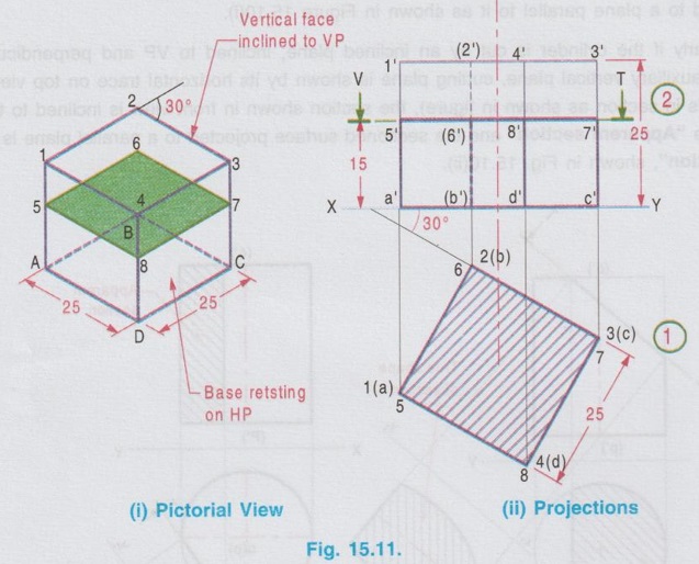
The pictorial view of the cube with cutting plane is shown in Fig. 15.11(i), cut by a Horizontal plane 5-6-7-8, 15 mm above HP.
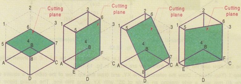
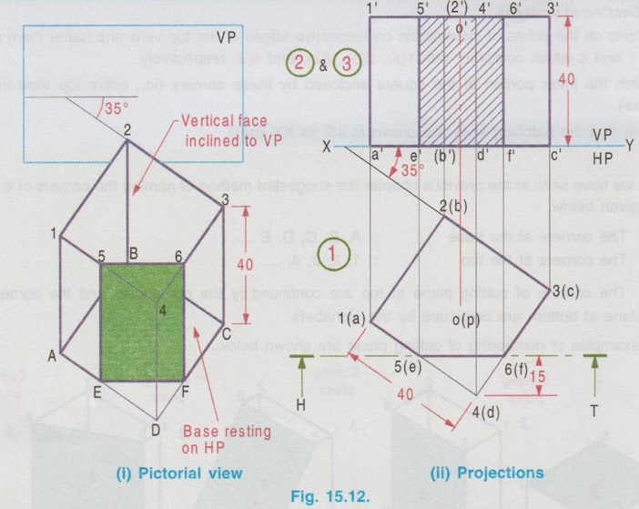
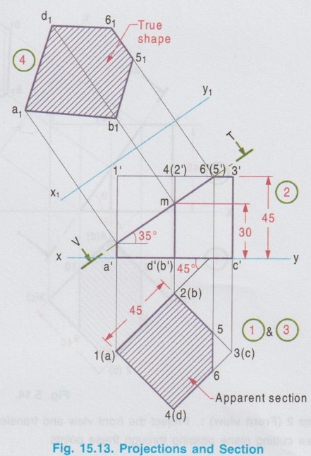
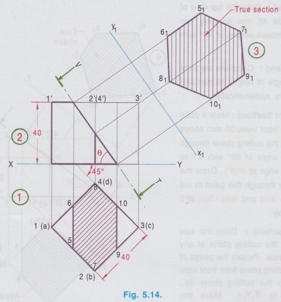
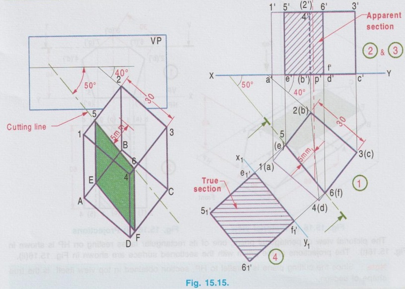
SECTIONS OF CUBE Example 1: A cube of side 25 mm rests on HP such a way that one of its faces with a vertical face inclined at 30° to VP. A plane parallel to HP and perpendicular to VP cuts the cube 15 mm above HP. Draw its front view and sectioned top view. The pictorial view of the cube with cutting plane is shown in Fig. 15.11(i), cut by a Horizontal plane 5-6-7-8, 15 mm above HP. Draw the projections of full solid first as described in the previous chapter without considering the cutting plane and then draw the sectional views with the cutting plane. Construction of Projections (Fig. 15.11 ii) Step 1 (Top view) 1. Draw the reference line XY. 2. Draw the top view of cube as a square of side 25 mm, keeping one of its edges inclined at 30° to XY (given in the problem). 3. Name the corners, showing the hidden corners within the bracket. Step 2 (Front view) 4. Draw the vertical projectors through the corners. 5. Complete the front view of the cube as a rectangle of height 25 mm (ie. side of cube) and name the corners. 6. Draw V.T of the section plane parallel to and 15 mm above the XY line. It cuts the edges of the cube in the front view as 5', (6'), 8' and 7'. Step 3 (Sectioned surface) 7. Project all the points of intersection on respective edges of the top view and name them as 5, 6, 7 and 8 which coincides with 1(a), 2(b), 3(c), and 4(d) respectively. 8. Hatch the inner portion of the square enclosed by these corners (ie., entire top view in this case). Note that the hatching lines are drawn at 45° to XY line. Note: 1) As we have seen in the previous chapter the suggested method of naming the corners of a solid is given below. The corners at the base : A, B, C, D, E .... The corners at the top : 1, 2, 3, 4, … The corners of cutting plane at top are continued by the numericals and the corners of cutting plane at bottom are continued by the alphabets. Some examples of numbering of cutting plane are shown below. 2. Examination point of view, the pictorial view is not required; However it is suggested to draw the pictorial view of the solid with cutting plane by free hand sketch and name the various corners. Then the projections can be drawn with a clear understanding of position of cutting plane and proper way of numbering on projections. 3. If the solid is resting on HP, (ie in simple position, axis perpendicular to HP and parallel to VP), always draw the top view first and then draw the front view. 4. When a solid is cut by a horizontal plane, the section seen on top view itself is its true shape. 5. Similarly if a solid is cut by a vertical plane, the section seen in front view itself is its true shape. 6. But if a solid is cut by an inclined plane (either inclined to HP or inclined to VP), the sections seen in topview (or) front view are only the apparent sections. Hence true shapes of these cases are to be drawn, by projecting the sectioned surface to a plane parallel to the cutting plane. Example 2: A cube of 40 mm side rests on HP on one of its faces with a vertical face inclined at 35° to VP. A plane perpendicular to HP and parallel to VP cuts the cube at 15 mm nearer to the observer. Draw the top view and the sectional front view. The pictorial view is shown in Fig. 15.12(i). Let the cutting plane be 5-6-F-E as shown in fig. The top view and the sectioned front view are shown in fig. 15.12(ii). Step 1 (Top view): Draw the reference line XY, and draw the top view of the cube as a square of side 40 mm with a side making an angle of 35° with XY using thin line. The cutting plane is perpendicular to HP. Hence it is seen as a straight line ie., draw the H.T of the plane which is a line parallel to XY at 15 mm nearer to the observer. Assume that the portion in between the cutting plane and the observer is removed. Hence draw the edges of the remaining portion using thicklines. Name the corners showing the hidden edges within the bracket. Step 2 (Front view): Complete the front view as a rectangle of height 40 mm using thin lines. Project the points of intersection of cutting plane with the edges 1(a) - 4(d) and 4(d) - 3(c) to the front view to intersect the top edge at 5' and 6' and the bottom edge at e' and f'. Name the other corners systematically. Step 3 (Section): Draw the outerlines and the visible edges of the section 5' - e' and 6' - f' using thicklines. Hatch the section enclosed by the points 5'-6'-f'-e'-5' using thin lines, inclined at 45° to XY. Since the cutting plane is perpendicular to HP, the section shown in front view is the true shape of the section. Example 3: A cube of side 45 mm is resting on HP with one of its faces. Two of its adjacent vertical faces make equal angles with VP. It is cut by a plane which is perpendicular to VP and inclined at 35° to HP and passing through a point on the axis at 30 mm from the base. Draw the front view, sectional top view and true shape of the section. Step 1 (Top view): Draw the top view of a square of side 45 mm keeping two adjacent edges makes angles of 45° with XY. Step 2 (Front view): Complete the front view as a rectangle of height 45 mm and name the corners systematically. Step 3 (Apparent Section): Mark a point m on the axis in front view, 30 mm above XY. Draw V.T of the cutting plane through this point at an angle of 35° with XY to intersect the top edge at 6'(5'). Draw the vertical projector through this point to cut the edges 2(b) - 3(c) and 4(d) - 3(c) at 5 and 6 respectively. Step 4 (True section): Draw the axis X1Y1 parallel to the cutting plane at any convenient distance. Project the points of intersection of cutting plane from front view perpendicular to the cutting plane (ie., perpendicular to X1Y1). Mark the corresponding points a1, b1, 51, 61 and d1 on the projectors drawn from the respective points. Note that the distance of a from reference axis xy is equal to the distance of a1 from the new reference axis X1Y1. Similarly the other points b1, 51 etc.. may be marked. Draw the outer edges of apparent section and true section using thick lines and hatch the area enclosed by these edges using thin lines drawn at an angle of 45°. Example 4: A cube of side 40mm resting on HP on one of its ends and cut by a plane in such a way that the true shape of the section is a regular hexagon. Draw front view, sectional top view and determine the inclination of the plane with HP. It is given the cube is resting on one of its ends and the true section is a regular hexagon, having six sides. To satisfy the above, the cube must be placed in such a way that two adjacent vertical faces are equally inclined to VP and the cutting plane shouild cut the six edges at their mid- heights. Step 1 (Top view): Draw a square of side 40mm as top view, keeping two sides equally inclined to XY. Mark the mid point of edges in top view as 5, 6, 9 and 10 and mid point of vertical edges 2-6 and 4-d as 7 and 8 respectively. Step 2 (Front view): Project the front view and transfer the points 5, 6, 7,....10 from topview and draw cutting plane passing through these points. Step 3 (True section): Draw a new reference line X1Y1 parallel to XY at convenient distance and draw perpendiculars through the points 5', 6' etc, and mark the points 51, 61 etc. on the corresponding projectors such that distance of 5 from XY is equal to distance 51 from X1Y1. Joining these points in proper sequence, true section of a regular hexagon is obtained. To Find angle of cutting plane with HP (θ) Measure the inclination of cutting plane V.T with XY. Example 5: A cube of side 30 mm rests on HP on one of its faces with a vertical face inclined at 40° to VP. A plane perpendicular to HP and inclined at 50° to VP cuts the cube, 5 mm away from the axis. Draw the top view and the sectional front view. Also draw the true shape of the section. Step 1 (Top view): Draw the top view of the cube as a square keeping one of the edges inclined at 40° to XY. Step 2 (Front view) : Project the points from top view and complete the front view. Mark the points as 1', 2' etc., and a', b' etc., Step 3 (Apparent section): Cutting plane is inclined to VP. Hence draw the H.T of cutting plane at 5 mm away from axis in top view (It is usual practice to remove the lesser portion of solid cut by the section plane and draw the projections for the remaining major portion) at an angle of 50° to XY. Mark the points cut by the H.T with the edges 1(a) - 2(b) and 4(d) - 3(c) at 5(e) and 6(f) respectively. (5 and 6 are the points cut by the plane with 1-2 and 4-3 respectively, where as e and f are the respective points cut by the plane with a-b and d-c edges). Project the points 5(e) and 6(f) in front view and mark the points 5', 6', e' and f'. Draw the lines with appropriate thickness and hatch the surface enclosed by 5'- 6'- f'-e' - 5' by thin lines at an angle of 45°, which is the apparent shape of the section. Step 4 (True section): Draw the axis X1Y1 parallel to the cutting plane at any convenient distance. Mark the points e'1, 5'1, 6'1 and f'1, on the respective projectors projected from the cutting plane such that the distance of e'1 from X1Y1 axis is equal to the distance of e' from xy axis and so on. Draw the boundary of true section using thick lines and hatch the surface enclosed using thinlines at an angle of 45°.1. Sections of Cube by a Horizontal plane
2. Section of cube by a vertical plane
3. Sections of cube by a plane inclined to HP and Perpendicular to VP
4. Section of Cubes by a plane inclined to VP and Perpendicular to HP
Engineering Graphics: Unit IV (a): Sections of Solids : Tag: : Construction, Steps, Example Problems | Engineering Graphics (EG) - Sections of cube
Related Topics
Related Subjects

Engineering Graphics
GE3251 eg 2nd semester | 2021 Regulation | 2nd Semester Common to all Dept 2021 Regulation