Engineering Graphics: Unit IV (a): Sections of Solids
Sections of cone
Construction, Steps, Example Problems | Engineering Graphics (EG)
Note that the circumference of 2, circle in top view is not divided into 8 (or) 12 equal parts as it is not required for either 11 apparent section (or) true section.
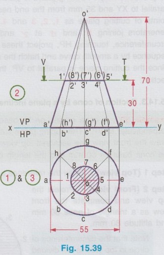
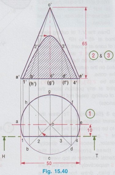
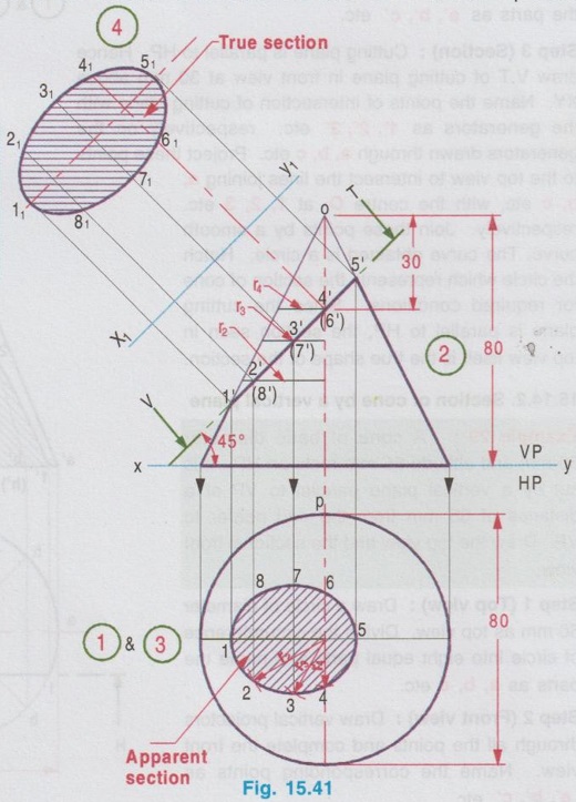
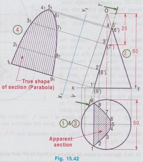
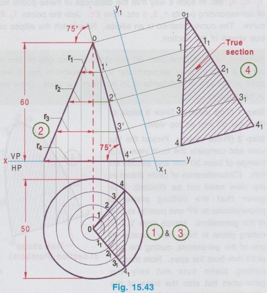
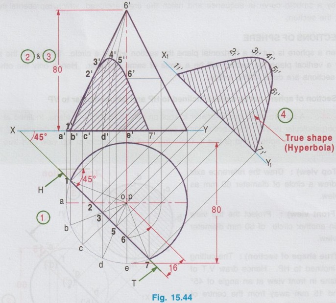
SECTIONS OF CONE Example 28 : A cone of base diameter 55 mm and altitude 70 mm rests on its base on HP. It is cut by a plane parallel to HP at 30 mm above the base. Draw the front view and sectional top view. Step 1 (Top view): As the axis of cone is perpendicular to HP, the true shape can be seen in top view. Hence draw the top view first, a circle of diameter 55 mm. Divide the circumference of circle into 8 equal parts and name the parts as a, b, c etc. Step 2 (Front view): Draw vertical projectors through all the points and complete the front view as a triangle of height 70 mm, equal to the length of axis of cone. Name the parts as a', b', c' etc. Step 3 (Section): Cutting plane is parallel to HP. Hence draw V.T of cutting plane in front view at 30 mm above XY. Name the points of intersection of cutting plane with the generators as 1', 2', 3' etc. respectively on the generators drawn through a, b, c etc. Project these points to the top view to intersect the lines joining a, b, c etc, with the centre O, at 1, 2, 3 etc. respectively. Join these points by a smooth curve. The curve obtained is a circle. Hatch the circle which represents the section of cone for required conditions. Since the cutting plane is parallel to HP, the section seen in top view itself is the true shape of the section. Example 29: A cone of base diameter 50 mm and altitude 65 mm rests on HP. It is cut by a vertical plane parallel to VP at a distance of 35 mm from the end nearer to VP. Draw the top view and the sectional front view. Step 1 (Top view): Draw a circle of diameter 50 mm as top view. Divide the circumference of circle into eight equal parts and name the parts as a, b, c etc. Step 2 (Front view): Draw vertical projectors through all the points and complete the front view. Name the corresponding points as a', b', c' etc. Step 3 (Section): Cutting plane is parallel to V.P. Hence draw H.T of cutting plane in top view, parallel to XY and 35 mm from the end nearer to VP. ie., 10mm from the axis. Mark the intersecting points of cutting plane as 1, 2, 3 and 4. Project these points to the front view to intersect the generators joining b' and d' at 2′ and 3′ respectively. Since the points 1 and 4 are on the circumference, touching HP, project these points to XY line. Join the points 1', 2', 3' and 4' in a sequence by a smooth curve and hatch the area enclosed. (The curve obtained is a regular hyperbola). Since the cutting plane is parallel to VP, the section seen in front view itself is the true shape of the section. Example 30: A cone resting on its base upon HP, is cut by a plane inclined at 45° to HP and perpendicular to VP. The cutting plane cuts the axis of the cone at a point 30 mm below the vertex. Draw the front view, the sectional top view and the true shape of the section. Take the diameter of the cone base as 80 mm and the length of axis is 80 mm. Step 1 (Top view): Draw the reference axis XY and draw a circle of diameter 80 mm as top view. Step 2 (Front view): Project the top view and complete the front view as a triangle of base 80 mm and altitude 80 mm. Note that the circumference of 2, circle in top view is not divided into 8 (or) 12 equal parts as it is not required for either 11 apparent section (or) true section. Draw the V.T of cutting plane inclined at 45° to HP, cutting the axis of cone at a point 30 mm below the vertex. Let 1' and 5' be the extreme points on the line of cutting, located on the outermost generators of the cone. Let the intermediate points be 2'(8'), 3'(7') and 4'(6'), located at any position along the line of cutting. (need not be at equal distances) Step 3 (Section): To draw the apparent section, points 1', 2' etc. are to be projected to the top view. Point 1' and 5' on the extreme generator, hence project directly. Let these projectors cut the horizontal diameter in top view at 1 and 5 respectively. To find the point 2 in plan, draw horizontal line through 2' from the axis of cone in front view till it intersect the outermost generator. Measure this distance as the radius of cone as r2. With O (centre of circle in top view) as centre and radius r2 draw an arc to cut the vertical projector drawn through 2' to locate the point 2 in top view. Similarly locate the remaining points 3 and 4 and join them with a smooth curve. Hatch the area enclosed by this curve which represents the apparent shape of section. Step 4 (True shape): Draw another axis X1Y1 parallel to XY at any convenient distance. Draw the projectors through the points on cutting plane, perpendicular to the cutting plane. Locate the points 11, 21, 31 etc. in such a way that the distances of these points from X1Y1 are equal to the distances of corresponding points 1, 2, 3 etc. from XY. Join the points 11, 21, 31 etc. in sequence by a smooth curve. The curve obtained is an ellipse. Now hatch the ellipse using thin lines which represents the true shape of the section. Example 31: A cone base 50 mm diameter and axis 60 mm long rests with its base on HP. It is cut by a section plane perpendicular to VP, parallel to one of the generators and passing through a point on the axis at a distance of 25 mm from the apex. Draw the sectional top view and true shape of the section. Step 1 (Top view): Draw a circle of diameter 50 mm as top view. Step 2 (Front view): Project the top view and complete the front view as a triangle of base 50 mm and altitude 60 mm. (Circumference of circle drawn in top view need not be divided). It is given that the cutting plane is perpendicular to VP and parallel to one of the generators. Hence draw V.T of cutting plane in front view, parallel to one of the generators, cutting the axis at 25 mm from the apex. Note that the cutting plane cuts not only the generators but also the base of the cone in front view. Let it be 1' (9'). Mark the intermediate points on cutting plane as 2' (8'), 3'(7'), 4'(6') and 5' at any position along the line of cutting (need not be at equal distances). Step 3 (Section): Project these points to the top view and mark the points 1, 2, 3 etc., as explained in the previous problem. Join these points in a sequence by a smooth curve and hatch the area enclosed, which represents the apparent shape of the section. Step 4 (True shape): Draw another reference axis X1Y1 parallel to cutting plane at any convenient distance. Draw perpendiculars through all the points on the cutting plane, perpendicular to the cutting plane. Measure the distance of point 1 from XY axis and plot the same distance from the axis X1Y1 on the perpendicular drawn from 1'. Let the point be 11. Similarly other points 21, 31 etc. to be marked and join these points by a smooth curve. The curve obtained is a parabola. Hatch the parabola, which represents the true shape of the section. The projections are shown in Fig. 15.42. Example 32: A cone of base diameter 50mm and altitude 60mm rests on its base on HP. It is cut by a section plane perpendicular to VP and inclined at 75° to HP, passing through the apex. Draw the front view, sectional top view and true shape of the section. Step 1 (Top view): Draw a circle of diameter 50mm as top view (note that division of circumference is not necessary). Step 2 (Front view): Project the top view and draw the front view as a triangle of height 60mm. Draw section line V-T at an angle of 75° with HP and passing through apex. Divide the cutting plane into any number of parts, (say 4) need not equal, and mark as 1', 2', 3' and 4'. Step 3 (Section) : Transfer the points 1', 2', 3' and 4' to the top view by circle method. (For example in front view draw horizontal projector through 1' to the extreme generator and note the point of intersection. Measure the horizontal distance of this point from axis and taking this measurement as radius draw a circle in top view with O as centre. Then draw vertical projector through 1' to cut the circle drawn at 1 and 11. Similarly other points are marked) Join these points and hatch the area enclosed which gives the sectional top view. Step 4 (True section): Draw a new reference line X1Y1 and project the true shape of section as shown in Fig.15.43. Example 33: A cone 80 mm base diameter and axis 80 mm long is resting upon its base on HP. It is cut by a vertical plane, perpendicular to HP, and inclined at an angle 45° to VP and 16 mm away from the axis. Draw top view, sectional front view and true shape of the section. Step 1 (Top view): Draw a circle of diameter 80 mm as top view. Step 2 (Front view): Project the top view and complete the front view as a triangle of altitude 80 mm. Step 3 (Section): Draw H.T of cutting plane in top view 45° inclined to XY and 16 mm away from the axis. Let the cutting plane intersects the circumference of circle at 1 and 7 (assumed to be divided into six parts). Divide the circumference of circle in between the points 1 and 7 (ie., on the portion of cone removed after cutting) also into 6 parts (need not be equal parts) and name the dividing points as a, b, c, d and e. Project the points a, b, c, d, e, 1, and 7 to the front view to intersect XY at a', b' etc., (since all the points are on the circumference, marked on XY line). Join the points a', b' etc. with apex of cone which are the generators of cone. Join the points a, b, c, d and e to the centre of circle O in top view to intersect the cutting plane at 2, 3, 4, 5 and 6 respectively. Project the points 2, 3, 4, 5 and 6 to the generators drawn through the points a, b, c, d and e respectively in front view to intersect at 1', 2', 3', 4' and 5' respectively. To mark 6' : with O as centre and 0-6 as radius draw an arc to cut the horizontal diameter and then draw vertical projector to cut the extreme generator. From this point draw horizontal line to cut the axis at 6'. Join the points 1', 2', 3'.... 7' by a smooth curve in sequence and hatch the area enclosed which represents the section of cone for the given conditions. Step 4 (True section): Draw another axis X1Y1 parallel to XY at any convenient distance. Project all the points on cutting plane in top view, perpendicular to the cutting plane. Measure the distance of point 1' from XY and mark the same distance from X1Y1 on the projector drawn through 1. Let it be 1'1. Similarly the other points 2'1, 3'1 etc. are to be marked. Join these points 1'1, 2'1, 3'1, 4'1, 5'1, 6'1 and 7'1 by a smooth curve in sequence and hatch the area enclosed, which represents the true shape of the section.1. Section of cone by a horizontal plane
2. Section of cone by a vertical plane
3. Section of cone by a plane inclined to HP and perpendicular to VP
4. Section of cone by a plane inclined to VP and perpendicular to HP
Engineering Graphics: Unit IV (a): Sections of Solids : Tag: : Construction, Steps, Example Problems | Engineering Graphics (EG) - Sections of cone
Related Topics
Related Subjects

Engineering Graphics
GE3251 eg 2nd semester | 2021 Regulation | 2nd Semester Common to all Dept 2021 Regulation