Engineering Graphics: Unit IV (a): Sections of Solids
Section Plane, Section and Sectional View
Engineering Graphics (EG)
A solid is cut by an imaginary plane and the portion of the solid in between the imaginary plane and observer is assumed to be removed to show the internal details of the solid.
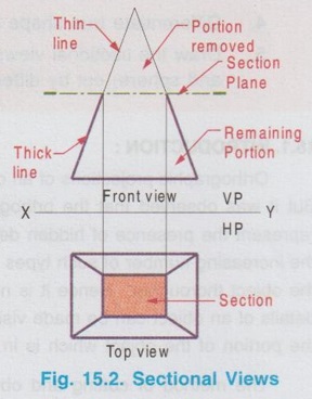
SECTION PLANE, SECTION AND SECTIONAL VIEW A solid is cut by an imaginary plane and the portion of the solid in between the imaginary plane and observer is assumed to be removed to show the internal details of the solid. The imaginary plane which is used to cut the solid is called 'Section Plane' (or) 'Cutting Plane'. The surface of the object seen while cutting by the section plane is called the section'. is called the `section'. After cutting the solid by an imaginary plane and removing the portion of solid in between the section plane and observer, the projections of the remaining portion are drawn. The projections of sectioned surface along with the remaining portion on the reference plane is called 'Sectional view'. Fig. 15.1. shows the pictorial view of a rectangular pyramid cut by a section plane (or cutting plane), Section the cutting plane being parallel to Plane the base (or perpendicular to the axis) at a height h from the base. The surface of the pyramid seen while cutting is known as `Section' (or) `Sectioned Surface'. Pictorial view of the section along with the remaining portion of pyramid, after removing the portion of pyramid above the section is shown in Fig. 15.1 (ii). The projections (Front view and top view) of this remaining portion of pyramid along with the section are drawn in Fig. 15.2, known as sectional views. (These views are drawn in First angle orthographic projections). It is to be noted that, though the sectional views are drawn for the remaining portion of solid with the sectioned surface, it is usual practice to draw also the portion of solid removed by section plane. To differentiate between the remaining portion and the portion removed, it is usual practice that the orthographic views of full solid are drawn first and then the visible edges of the remaining portion are drawn by continuous thicklines and the portion removed by cutting plane are drawn with continuous thin line as shown in Fig. 15.2. Similarly some guidelines are to be followed to represent cutting plane, sectioned surface and to draw the sectional views. These guidelines are presented in the following articles.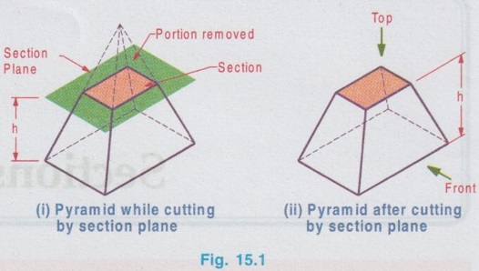
 f
f
Engineering Graphics: Unit IV (a): Sections of Solids : Tag: : Engineering Graphics (EG) - Section Plane, Section and Sectional View
Related Topics
Related Subjects

Engineering Graphics
GE3251 eg 2nd semester | 2021 Regulation | 2nd Semester Common to all Dept 2021 Regulation