Theory of Machines: Unit I: Kinematics of Mechanisms
Rubbing velocity at a pin joint
Kinematics of Mechanisms - Theory of Machines
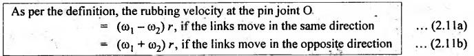
The rubbing velocity at a pin joint is defined as the algebraic sum between the angular velocities of two links which are connected by pin joints, multiplied by the radius of the pin.
RUBBING VELOCITY AT A PIN JOINT
• The
rubbing velocity at a pin joint is defined as the algebraic sum between the
angular velocities of two links which are connected by pin joints, multiplied
by the radius of the pin.
• Consider
two links 1 and 2 which are connected by a pin joint at O, as shown in Fig.2.6.
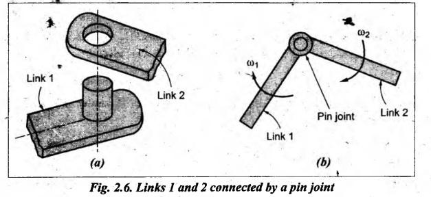
Let
r
= Radius of the pin at the joint,
ω1
= Angular velocity of link 1, and
ω2
= Angular velocity of link 2.
Note
When the pin connects
one sliding member and the other turning member (for example, at gudgeon pin of
the connecting rod), the rubbing velocity = ω • r, because the angular
velocity of the sliding member is zero.
Example 2.1
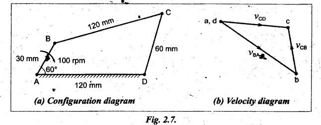
In a four-bar chain ABCD, AD is fixed and is 120 mm long. The
crank AB is 30 mm long and rotates at 100 rpm clockwise. While the link CD = 60
mm oscillates about D, BC and AD are of equal length. Find the angular velocity
of link CD when angle BAD = 60°
Given data:
AD
= 120 mm (fixed); AB = 30 mm; NBA = 100 rpm (CW); CD = 60 mm; BC =
AD; ![]() BAD = 60°.
BAD = 60°.
Solution: Relative velocity method
Procedure:
Step 1: Configuration
diagram: First of all, draw the configuration
diagram, to some suitable scale (say, 1 cm = 20 mm), as shown in Fig.2.7(a),
using the procedure given below.
1.
With suitable scale draw AD and AB with an angle 60°.
2.
From point B, draw an arc of 120 mm radius.
3.
From point D, draw another arc of radius 60 mm.
4.
Take the intersecting point as C, and join 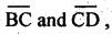 as shown in Fig.2.7(a).
Step 2: Velocity of
input link:
Speed
of input link, NBA = 100 rpm (given)
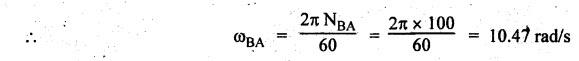
Velocity
of the input link AB is given by
vBA=
ωBA × AB = 10.47 × 0.03 = 0.3141 m/s
Step 3: Velocity
diagram: Now draw the velocity diagram, as
shown in Fig.2.7(b), to some suitable scale (say, 1 cm = 0.1 m/s), using the
procedure given below.
1.
Since the link AD is fixed, the velocity of points A and D are zero and they
are represented by one point (a, d) in the velocity diagram.
2.
From point a, draw vector ab perpendicular to BA to represent the velocity of B
with respect to A (i.e., vBA or vB)
such that vector ab = vBA = vB .
3.
From point b, draw vector bc perpendicular CB to represent the
velocity of C with respect to B (i.e., vCB).
4.
Now from point d or a, draw vector dc perpendicular to CD
to represent the velocity of C with respect to D (i.e., vCD
or vC).
5.
The vectors bc and dc intersect at point c. The vector dc
= vCD = vC.
Step 4: Angular
velocity of link CD:
By
measurement from the velocity diagram, we get
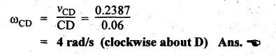
Velocity
of link CD, vCD = 0.2387 m/s
The
angular velocity of link CD is given by
Example 2.2
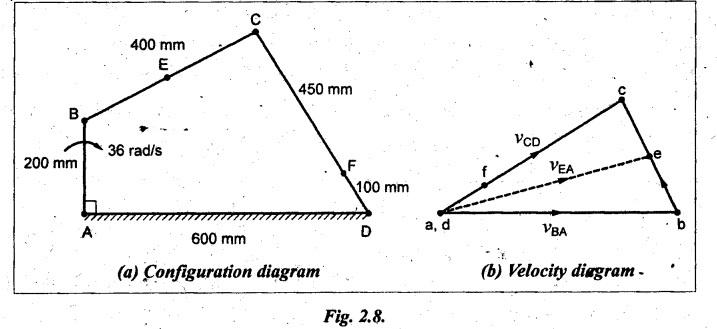
In a four-link mechanism, the crank AB rotates at 36 rad/s. The
lengths of the links are AB = 200 mm, BC= 400 mm, CD = 450 mm and AD = 600 mm.
AD is the fixed link. At the instant when AB is at right angle to AD, determine
the velocity of
(i) the mid-point of link BC.
(ii) a point on link CD, 100 mm from the points connecting the
links CD and AD.
Given data:
ωBA
= 36 rad/s; AB = 200 mm; BC = 400 mm; CD = 450 mm; AD = 600 mm (fixed); ![]() BAD = 90°.
BAD = 90°.
Solution: Relative velocity method
Procedure:
Step 1: Configuration
diagram: First of all, draw the configuration
diagram, to some suitable scale (say, 1 cm = 100 mm), as shown in Fig.2.8(a),
using the procedure given in Example 2.1.
Step 2: Velocity of
input link:
Angular
velocity of input link, ωBA = 36 rad/s (given)
⸫
Velocity of the input link AB is given by
VBA = ωBA • AB = 36 × 0.27.2 m/s
Step 3: Velocity
diagram: Now draw the velocity diagram, as
shown in Fig.2.8(b), to some suitable scale (say, 1 cm = 1.5 m/s), using the
procedure given in Example 2.1.
Step 4: Velocities of
various links:
(i)
Velocity of point E on link BC:
Locate
the point e at the centre of vector bc to find velocity of mid point of link
BC. Join e and a. Now the vector ea gives the velocity of the mid point E.
By
measurement from the velocity diagram, we get
Velocity
of mid-point E of ink BC with respect to 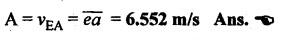
(ii)
Velocity of point F on link CD:
By
measurement from velocity diagram, we get
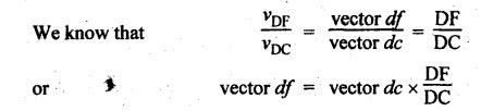
vCD
= 6.624 m/s
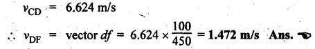
Now
the point f on the velocity diagram can be located as shown in Fig.2.8(b).
Example 2.3
The crank of a slider-crank mechanism is 15 cm and the
connecting rod is 60 cm long. The crank makes 300 rpm in the clockwise
direction. When it has turned 45° from the inner dead centre position,
determine:
(i) Velocity of slider.
(ii) Angular velocity of connecting rod.
(iii) Linear velocity of mid-point of the connecting rod.
[A.U.,
Nov/Dec 2012]
Given data:
OA
15 cm; AB = 60 cm; NOA = 300 rpm (clockwise); ![]() AOB = 45°.
AOB = 45°.
Solution: Relative velocity
method.
Procedure:
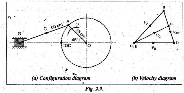
Step 1: Configuration
diagram: First of all, draw the configuration
diagram, to some suitable scale (say, 1 cm = 75 mm), as shown in Fig.2.9(a),
using the procedure given below.
1.
First draw line of stroke.
2.
At any point O on the line of stroke, draw a crank OB of length 15 cm and θ =
45°.
3.
From point A, draw an arc of radius 60 cm to cut the line of stroke, then the
cutting point be B.
4.
Locate mid-point C on AB at a distance AC = 30 cm.
Step 2: Velocity of
input link:
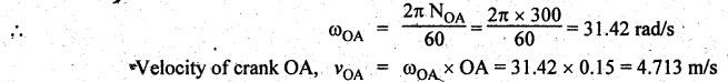
Speed
of input link (i.e., crank), NOA = 300 rpm (given)
Step 3: Velocity
diagram: Now draw the velocity diagram, as
shown in Fig.2.9(5), to some suitable scale (say, 1 cm = 1.5 m/s), using the
procedure given below.
1.
From any arbitrary point o, draw vector oa perpendicular to the link OA.
2.
Since link AB is a rigid link, therefore the velocity of B with respect to A is
perpendicular to AB. Now from point a, draw vector ab perpendicular to
AB to represent the velocity of B with respect to A (i.e., vBA).
3.
Since the velocity of slider B relative to O (i.e., vBO)
is along the line of stroke OB, so from point o, draw vector parallel to
OB.
4.
The vectors ab and ob intersect at point b.
Step 4: Velocity of
various links:
(i)
Velocity of slider B:
By
measurement from the velocity diagram, we get
Velocity
of slider, vB = vob = vector ob = 4
m/s Ans. ![]()
(ii)
Angular velocity of connecting rod AB:
By
measurement from the velocity diagram, we get
Velocity
of connecting rod AB, vAB = vector ba = 3.35 m/s
The
angular velocity of connecting rod AB is given by

(iii)
Linear velocity of mid-point of the connecting rod:
In
order to find the velocity of mid-point of the connecting rod, divide the
vector ba at c in the same ratio as C divides AB, in the configuration diagram.
In this case, since C is the mid- point of AB, therefore c is also
mid-point of vector ba.
Now
by measurement from the velocity diagram, we get
Velocity
of mid-point C, vC = vector oc = 4.1 m/s Ans.![]()
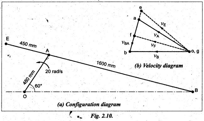
Example 2.4
In a slider-crank mechanism, the crank is 480 mm long and
rotates at 20 rad/s in the counter clockwise direction. The length of the
connecting rod is 1600 mm. When the crank runs 60° from the inner-dead centre,
determine
(i) The velocity of the slider.
(ii) The velocity of a point E located at a distance 450 mm on
the connecting rod extended.
(iii) The position and velocity of a point F on the connecting
rod having least absolute velocity.
(iv) The angular velocity of the connecting rod.
(v) Thễ velocity of rubbing at the pins of the crank shaft,
crank and the cross-head having diameters 80, 60 and 100 mm respectively.
Given data:
Crank,
OA = 480 mm; ωOA = 20 rad/s (counter clockwise); Connecting rod, AB
= 1600 rpm; θ = 60°
Solution: Relative velocity
method.
Procedure:
Step 1: Configuration
diagram: First of all, draw the configuration
diagram, to some suitable scale (say, 1 cm = 160 mm), as shown in Fig.2.10(a),
using the procedure given in Example 2.5.
Step 2: Velocity of
input link:
Angular
velocity of input link (ie., crank), ωOA = 20 rad/s (given)
Velocity
of the crank is given by
vOA
= ωOA × OA = 20 × 0.48 = 9.6 m/s Ans.![]()
Step 3: Velocity
diagram: First of all, draw the velocity
diagram (Aoab), as shown in Fig.2.10(b), to some suitable scale (say, 1
cm = 2.5 m/s), using the procedure given in Example 2.5.
Step 4: Velocity of
various links:
(i)
Velocity of slider B:
By
measurement from the velocity diagram, we get
Velocity
of slider, vB = vBO = vector ob = 9.6
m/s Ans. ![]()
(ii)
Velocity of point E:
To
locate point e: The velocity of point E
on the connecting rod AB can be determined with the help of below relation.
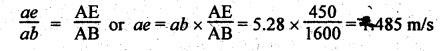
Now
extend the ab vector and locate point e at 1.485 m/s from a. Join o
and e.
Now,
by measurement from the velocity diagram, we get
Velocity
of point E, vE = vEO = vector eo = 10.08
m/s Ans. ![]()
(iii) Least absolute velocity of connecting rod at F:
To
locate point f: To locate least absolute
velocity of connecting rod, draw perpendicular line from o to vector ab.
Since the length of of will be the least, therefore point ƒ represents the
required position F on the connecting rod.
Velocity
of point F: By measurement from the velocity
diagram, we get
Velocity
of point F, vF = vFO = vector of = 9.36
m/s Ans. ![]()
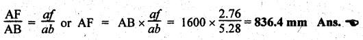
Position
of F on AB: The position of point F on the
connecting rod AB can be obtained as below.
(iv)
Angular velocity of connecting rod:
By
measurement from the velocity diagram, we get
Velocity
of connecting rod, AB, vAB = vector ab = 5.28 m/s
The
angular velocity of connecting rod AB is given by

(v)
Velocity of rubbing:
Given:
dO = 80 mm; dA = 60 mm; dB
= 100 mm
(a)
Velocity of rubbing at the crank-shaft pint O:
We
know that velocity of rubbing at the crank-shaft pin
=
ωOA × rO = 20 × (0.08/2) = 0.8 m/s Ans. ![]()
Velocity
of rubbing at the crank pin A
=
(ωOA + ωAB) rA (⸪ links OA and AB
rotate in the opposite direction)
=
(20 + 3.3) × (0.06/2) = 0.699 m/s Ans. ![]()
Velocity
of rubbing at the cross-head B
=
ωAB × rA ( ⸪ At the cross-head, ωslider is
zero as slider does not rotate)
=
3.3 × (0.12) = 0.165 m/s Ans. ![]()
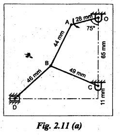
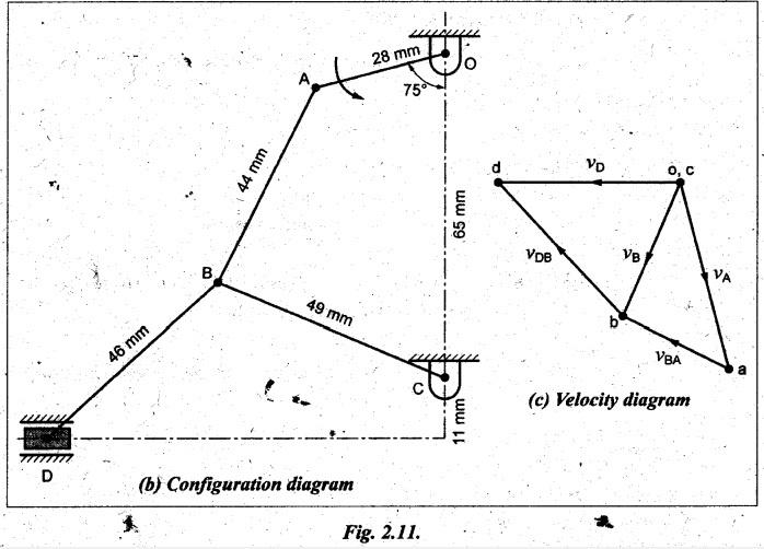
Example 2.5
In Fig.2.11(a); the angular velocity of the crank OA is 500 rpm.
Determine the linear velocity of the slider D and the angular velocity of the
link BD, when the crank inclined at an angle of 75° to the vertical. The
dimensions of various links are: BD = 46 mm, OA = 28 mm, AB = 44 mm and BC = 49
mm.
The centre distance between the centres of rotation O and C is
65 mm. The path of travel of the slider is 11 mm below the fixed point C. The
slider moves along a horizontal path and OC is vertical.
Given data:
NOA
= 500 rpm; ![]() BOA = 75°; BD = 46 mm; OA = 28 mm; AB = 44 mm; BC= 49 mm; OC
= 65 mm
BOA = 75°; BD = 46 mm; OA = 28 mm; AB = 44 mm; BC= 49 mm; OC
= 65 mm
Solution: Relative velocity
method.
Procedure:
Step 1: Configuration
diagram: First of all, draw the configuration
diagram, to some suitable scale (say, full scale), as show in Fig.2.11(b),
using the procedure given below.
1.
First draw a vertical axis line and locate point O and C on it such that OC =
65 mm.
2.
From point O, draw a crank OA of length 28 mm at 75° to the vertical axis.
3.
From point A, draw an arc of radius 44 mm and from point C, draw an arc of
radius 49 mm to cut each other, then locate the cutting point as B.
4.
Now, from point B, draw 46 mm length line to the horizontal axis which is 11 mm
below the point C, so that to locate point D as shown in Fig.2.11.
Step 2: Velocity of
input link:
Speed
of input link (i.e., crank OA), NOA = 500 rpm (given)
Velocity
of crank OA is given by
vOA
= ωOA × OA = 52.36 × 0.028 = 1.466 m/s
Step 3: Velocity
diagram: Now draw the velocity diagram, as
shown in Fig.2.11(c), to some suitable scale (say, 1 cm = 0.350 m/s), using the
procedure given below.
1.
Since the link OC is fixed, the velocity of point O and C are zero and they are
represented by one point (o, c) in the velocity diagram.
2.
From point o, draw vector oa perpendicular to the link OA such
that vector oa = vOA = 1.466 m/s.
3.
From point a, draw vector ab perpendicular to AB to represent the velocity of B
with respect to A. Also from point c, draw vector cb perpendicular to BC to
represent the velocity of B with respect to C.
4.
The vectors ab and cb intersect at point b.
5.
Since the piston reciprocates in the horizontal line, draw a line parallel to
the horizontal axis at o.
6.
Now from point b, draw a vector bd perpendicular to BD to pass
through the horizontal vector. The intersecting point thus obtained is d.
Step 4: Velocity of
various links:
(i)
Linear velocity of slider D:
By
measurement from the velocity diagram, we get
Velocity
of slider, vD = vOD = vector od = 1.32
m/s Ans. ![]()
(ii)
Angular velocity of link BD:
By
measurement from the velocity diagram, we get
vBD
= vector bd = 1.374 m/s
The
angular velocity of link BD is given by

Theory of Machines: Unit I: Kinematics of Mechanisms : Tag: : Kinematics of Mechanisms - Theory of Machines - Rubbing velocity at a pin joint
Related Topics
Related Subjects

Theory of Machines
ME3491 4th semester Mechanical Dept | 2021 Regulation | 4th Semester Mechanical Dept 2021 Regulation