Hydraulics and Pneumatics: Unit IV: Pneumatic and Electro Pneumatic Systems
Rotary vane compressor
Pneumatic and Electro Pneumatic Systems - Hydraulics and Pneumatics
The rotary vane type compressors are used in applications where low-pressure and low- volume are needed.
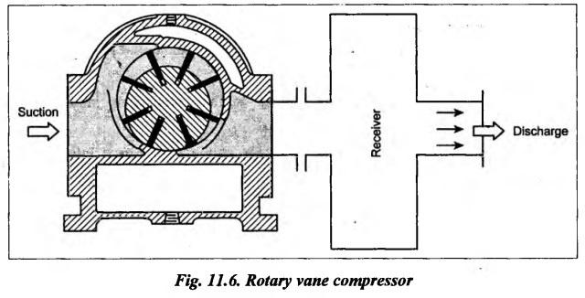
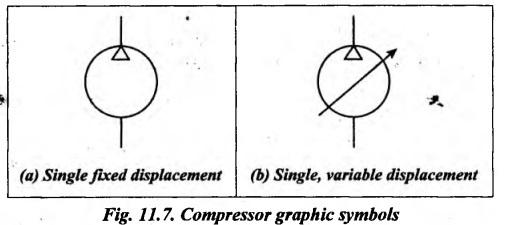
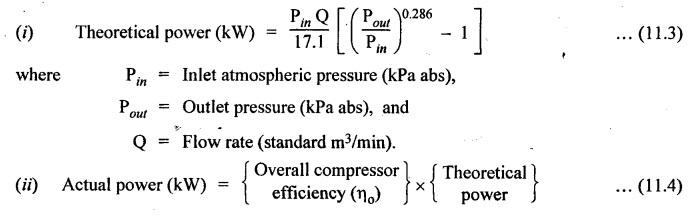
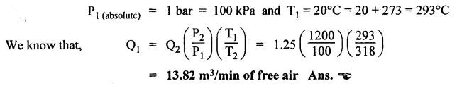
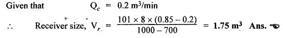
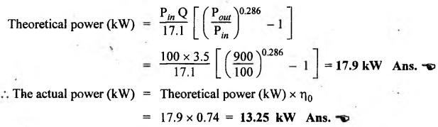
ROTARY VANE COMPRESSOR The rotary vane type compressors are used in applications where low-pressure and low- volume are needed. For example, they are used for instrument and other laboratory-type air needs. The construction and operation of a rotary vane compressor is very much similar to a hydraulic vane pump described in Section 4.12. A typical sliding-vane-type rotary compressor is illustrated in Fig.11.6. It consists of a rotor located eccentrically in a cylindrical outer casing. The rotor carries a set of spring-loaded vanes in the slots of the rotor, as shown in Fig.11.6. The air at atmospheric pressure is entrapped between two vanes. As the rotor rotates, the entrapped air is compressed between the vanes and then discharged through a port to the receiver. The symbolic representation of compressors are shown in Fig.11.7. 1. Rotary vane compressors are pulse free and therefore can be used without a receiver if needed. 2. They are smaller in size and lighter in weight. 3. They can work at high speed. The rotary vane type compressors are available with capacities upto 3000 m3/hr and pressures of 3 to 10 bars. Air compressors are generally specified/rated by the following: 1. Outlet pressure of air that can be delivered by the compressor, 2. Capacity or volume of air that can be delivered by the compressor, and 3. Compressor configuration and cylinder geometry. Q1 and Q2 = Volume flow rate of air at the compressor inlet and outlet respectively (m3/min), P1 and P2 = Absolute pressure of air at the compressor inlet and outlet respectively (kPa abs), And T1 and T2 = Absolute temperature of air at the compressor inlet and outlet respectively (°K). The air receiver size can be determined by using the following equation : where Vr = Receiver size (m3),. t = Time that receiver can supply required amount of air (min), Qr = Consumption rate of pneumatic system (standard m3/min)*, Qc = Output flow rate of compressor (standard m3/min), ♣ Pmax = Maximum pressure level in receiver (kPa), and Pmin = Minimum pressure level in receiver (kPa). The theoretical power required to drive an air compressor can be determined by using the following equations : • Standard m3/min means the inlet air volume (in m3/min) is at the standard atmospheric conditions of 1.013 bar and 20°C. Example 11.1 Air is used at a rate of 1.25 m3/min from a receiver at 45 °C and 12 bar gauge. How many standard m3/min of free air must the compressor provide ? Given Data: Q2 = 1.25 m3/min; T2 = 45°C = 45 + 273 = 318 K; P2 (gauge) = 12 bar or P2 (absolute) = 12 + 1 = 13 bar = 1300 kPa Solution: It is given that standard free air is used as the inlet. So the stàndard That means, the compressor must receive atmospheric air (1 bar and 20°C) at a rate of 13.82 m3/min in order to deliver air (12 bar and 45°C) at 1.25 m3/min. Example 11.2 (i) Calculate the required size of a receiver that must supply air to a pneumatic system consuming 0.85′′ standard m3/min for 8 min between 10 bar and 7 bar before the compressor resumes operation. (ii) What size is required if the compressor is running and delivering air at 0.2 standard m3/min ? Given Data Qr = 0.85 m3/min; t = 8 min; Pmax = 10 bar 1000 kPa ; Pmin = 7 bar = 700 kPa. Solution: (i) Required receiver size before the compressor starts operation : Since compressor has not started its operation, the output flow rate of compressor, QC = 0. (ii) Required receiver size when the compressor is running and delivering air at 0.2 standard m3/min: Example 11.3 Determine the actual power required to drive a compressor that delivers air at 3.5 standard m3/min at .8 bar gauge. The overall efficiency of the compressor is 74%. Given Data : Q = 3.5 m3/min; Pout (gauge) = 8 bar or P out (abs) = 8 + 1 = 9 bar = 900 kPa; ηo = 74%. Solution: Since standard atmospheric air is the inlet air, Pin (abs) = 1 bar = 100 kPa.1. Construction
2. Operation
3. Graphic Symbol
4. Advantages
5. Ranges
6. Specification of Compressors (Selection Criteria for Compressors)
7. Analysis of Air Capacity Rating of Compressors

8. Analysis of Sizing of Air Receivers

9. Analysis of Power Required to Drive Compressors

Hydraulics and Pneumatics: Unit IV: Pneumatic and Electro Pneumatic Systems : Tag: : Pneumatic and Electro Pneumatic Systems - Hydraulics and Pneumatics - Rotary vane compressor
Related Topics
Related Subjects

Hydraulics and Pneumatics
ME3492 4th semester Mechanical Dept | 2021 Regulation | 4th Semester Mechanical Dept 2021 Regulation