Theory of Machines: Unit II: Gears and Gear Trains
review and summary
Gears and Gear Trains - Theory of Machines
Gears are toothed wheels used for transmitting motion and power from one shaft to another when they are not too far apart and when a constant velocity ratio is desired.
REVIEW AND SUMMARY • Gears are toothed wheels used for transmitting motion and power from one shaft to another when they are not too far apart and when a constant velocity ratio is desired. • Gear drive is called as positive drive, as it provides exact velocity ratio without any slip. • In any pair of gears, the smaller one is called pinion and the larger one is called gear or wheel or bull gear, irrespective of which is driving the other. • Classification of gears: I. Classification based on relative position of two shafts carrying gears A. Parallel axes gears: Spur gears, helical gears, herringbone gears; and rack and pinion B. Intersecting axes gears: Straight bevel gears and spiral bevel gears C. Skew axes gears: Hypoid gears, worm and worm wheel, and spiral gears II. Classification based on type of meshing of gears 1. External gears 2. Internal gears. • Spur gears have teeth parallel to the axis of rotation and are used for transmitting motion between two parallel shafts. • Helical gears have teeth inclined to the axis of rotation and are used for transmitting motion between two parallel shafts. • Herringbone gears, also known as double helical gears, consists of teeth having a right and left handed helix cut on the same blank. • The rack and pinion is used to convert rotary motion into reciprocating motion. • Bevel gears are used to transmit power between two intersecting shafts. • Hypoid bevel gears, also known as hypoid gears, are used for right angle in which the axes do not intersect. • Worm and worm wheel, also known as worm gears, are used to transmit power from one shaft to another which are non-intersecting and their axes normally right angles to each other. • Spiral gears, also known as crossed helical gears or skew gears, are used to transmit power between two non-intersecting non-parallel shafts. • The size of the gear is usually specified by the pitch circle diameter. • The module is the index of tooth size. where D = Diameter of pitch circle, and T = Number of teeth on gear. • pppppppppppp where NA and NB = Speed of driving and driven gears respectively, TA and TB = Number of teeth on driving and driven gears respectively, and dA and dB = Pitch circle diameters of driving and driven gears respectively. • ppppppppppppp Where TP and TG = Number of teeth on pinion and gear wheel respectively, and r and R = Pitch circle radii of pinion and gear wheel respectively. • Law of gearing: The law of gearing states that for maintaining constant angular velocity ratio between two meshing gears, the common normal of the tooth profiles, at all contact points within mesh, must always pass through a fixed point on the lines of centres, called pitch point. • Velocity of sliding is the velocity of one tooth relative to its mating tooth along the common tangent at the point of contact. • Gear profiles which can satisfy the law of gearing are known as conjugate profiles. • The most common forms of tooth profiles are: 1. Cycloidal tooth profile, and 2. Involute tooth profile. • The involute gears are most commonly used in actual practice as compared to the cycloidal gears. • The four types of tooth profiles that are used for interchangeability are: 1. 14 ½° composite system, 2. 14½° full depth involute system, 3. 20°full depth involute system, and 4. 20° stud involute system. • In actual practice, the 20°full depth involute system is widely used. • Formulae summary: pppppppppppp ppppppppppppp • The phenomenon when the tip of the tooth of gear will dig out or interfere with the flank portion of the tooth portion of the mating gear is known as interference. • When the tip of the gear tooth undercuts the root (flank) of the mating gear tooth, some portion of the flank will be removed. This process of removal of material due | to interference phenomenon is called undercutting. • The condition to check whether interference occurs or not given by Length of path of approach (KP) ≤ Maximum length of path of approach (MP) where MP = r sin ϕ • Minimum number of teeth on gear in order to avoid interference is given by ppppppppppppp • Minimum number of teeth on gear in order to avoid interference is given by pppppppppppppppp • Minimum number of teeth on pinion in order to avoid interference with rack is given by ppppppppppp where AR - Addendum coefficient of rack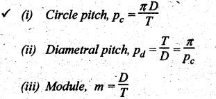
Theory of Machines: Unit II: Gears and Gear Trains : Tag: : Gears and Gear Trains - Theory of Machines - review and summary
Related Topics
Related Subjects

Theory of Machines
ME3491 4th semester Mechanical Dept | 2021 Regulation | 4th Semester Mechanical Dept 2021 Regulation