Hydraulics and Pneumatics: Unit II: Hydraulic Actuators and Control Components
review and summary
Hydraulic Actuators and Control Components - Hydraulics and Pneumatics
In this chapter, the purpose, construction, operation, and graphic symbols of various control valves required for proper functioning of the hydraulic systems have been discussed.
REVIEW AND SUMMARY • In this chapter, the purpose, construction, operation, and graphic symbols of various control valves required for proper functioning of the hydraulic systems have been discussed. • Hydraulic valves are devices used to control pressure, flow direction, or flow rate in hydraulic circuits. • Types of control valves: Three basic types of control valves, based on their function in the hydraulic system, are: 1. Directional control valves, 2. Pressure control valves, and 3. Flow control valves. • Valves configuration : Three essential types of valve configurations are : 1. Poppet (or seat) valves, 2. Sliding spool valves, and 3. Rotary spool valves. • The function of a directional control valve (DCV) is to control the direction of flow in a hydraulic circuit. • The check valves, also known as non-return valves, are used to allow free flow in only one direction, and to prevent any flow in the other direction. • The function of the position valve is to control the introduction of liquid to the lines of the system. • The position valves are usually described by their number of ports and positions. For example, a 4/2 valve has 4 ports and 2 positions. • The purpose, construction, and operation of various directional control valves- check valves, 2/2 valves, 3/2 valves, 4/2 valves, 4/3 valves, and shuttle valves-are discussed, in detail. • Shuttle valves, also known as double check valves, are used when control is required from more than one power source. • The pressure control valves are the devices used to control the fluid pressure in a system. • Types of pressure control valves : The three important types are : 1. Pressure limiting (or relief) valves, (a) Simple pressure relief valves, and (b) Compound pressure relief valves. 2. Pressure reducing (or regulating) valves, and 3. Sequence valves. • The pressure limiting valve, also known as the relief valve, protects a system from excessive fluid pressure over and above the design pressure limit. • The pressure regulating valve is used to supply a prescribed reduced outlet pressure in a circuit and to maintain it at a constant value. • The sequence valve is used to control the fluid flow to ensure several operations in a particular order of priority in the system. • Flow control valves, also known as volume-control valves, are used to regulate the rate of fluid flow to different parts of a hydraulic system. • Types of flow control valves: The two basic types of flow control valves are : 1. Non-pressure compensated flow control valves, and (i) Globe valves, and (ii) Needle valves. 2. Pressure compensated flow control valves. • This chapter also described the purpose, construction, operation, and graphic symbols of various pressure limiting valves and pressure sequence valves. • Formulae summary : • A servo control system is one in which a comparatively large amount of power is controlled by small impulses or command signals and any errors are corrected by feedback signals. • A system having a servo valve, servo amplifier and actuator connected together providing a closed loop feedback is known as a servomechanism. • Servo valves are DC valves having infinitely variable positioning capability. The servo valves are used to control not only the direction of fluid flow but also the amount of flow. • When servo values are coupled with feedback devices, they can be used to control the position, velocity, and acceleration of the actuator accurately. • Types of servo valves : The important types of servo valves are : 1. Mechanical-type servo valve, and 2. Electrohydraulic servo valve. (i) Single-stage servo valve, (ii) Two-stage servo valve, (iii) Jet pipe servo valve, and (iv) Flapper jet servo valve. • If the electrical signal is used as an input (or control) signal to control the hydraulic output, then it is known as electrohydraulic servo valve. • Proportional valves, similar to servo valves, use a variable force direct current solenoid to control the output from the main spool. Therefore the output is directly proportional to the input signal. • Types of proportional control valves: Three important types of proportional control valves are: (i) Proportional pressure relief valve, (ii) Proportional pressure reducing valve, and (iii) Proportional direction control valve. • Both proportional type pressure relief and pressure reducing valves work on the same principle as similar conventional pressure relief and pressure reducing valves, except that the adjustable springs are replaced by proportional solenoids. • Pressure switches are used to sense a change in pressure automatically, and opens or closes an electrical switch when a predetermined pressure is reached. KEY TERMS ONE SHOULD REMEMBER Hydraulic valves Control valves Valves configuration Poppet valves Sliding spool valves Rotary spool valves Directional control valves Check valves Non-return valves Position valves Hydraulics and Pneumatics Relief valves Capacity coefficient Simple pressure relief Servo valves valves Hydro mechanical servo valves Compound pressure relief valves Flow control valves Shuttle valves 2/2 DC valves 3/2 DC valves 4/2 DC valves 4/3 DC valves Non-pressure compensated flow control valves Pressure compensated flow control valves Volume control valves Electrohydraulic servo valves Single stage servo valves Two stage servo valves Jet pipe servo valves Flapper jet servo valves Proportional valves Proportional pressure relief valves Proportional pressure Speed control valves Pressure control valves Globe valves Pressure limiting valves Pressure reducing valves Butterfly valves Plug-type valves reducing valves Sequence valves Ball-type valves Counter balance valves Needle valves Unloading valves Pressure switch control valves Reservoir Proportional direction Hydraulic fuse Pressure switches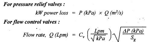
Hydraulics and Pneumatics: Unit II: Hydraulic Actuators and Control Components : Tag: : Hydraulic Actuators and Control Components - Hydraulics and Pneumatics - review and summary
Related Topics
Related Subjects

Hydraulics and Pneumatics
ME3492 4th semester Mechanical Dept | 2021 Regulation | 4th Semester Mechanical Dept 2021 Regulation