Manufacturing Technology: Unit III: Reciprocating Machine Tools
Reciprocating machine tools
Reciprocating Machine Tools - Manufacturing Technology
The one and only basic machine is a lathe. Except the lathe, other basic machines are shaper, planer, slotter, drilling, grinding, boring, milling and broaching machines.
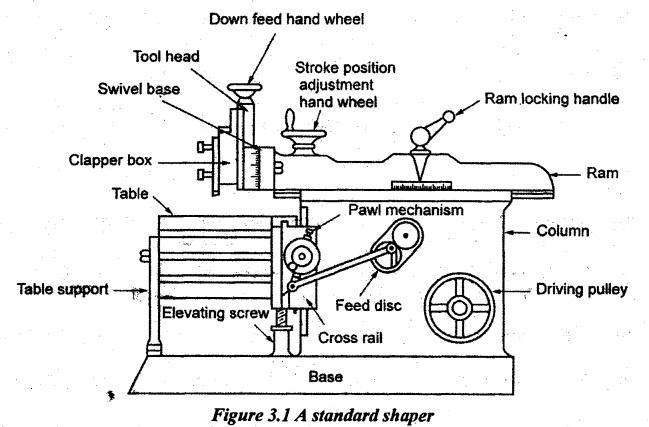
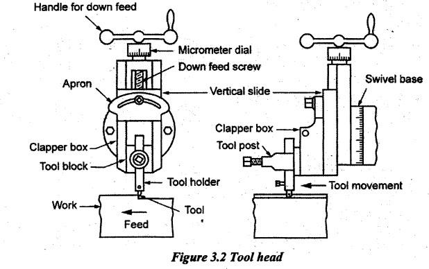
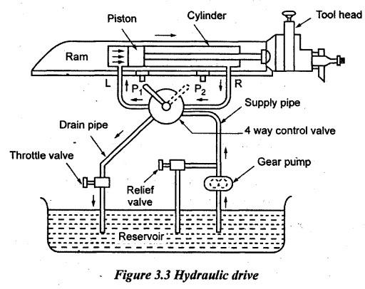
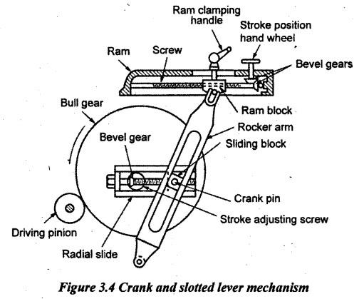
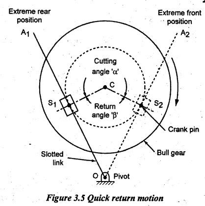
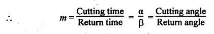
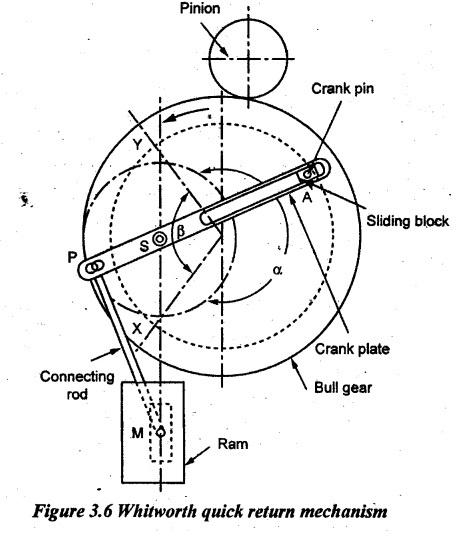
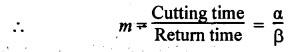
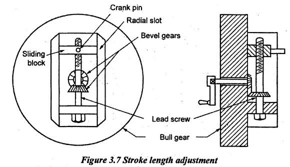
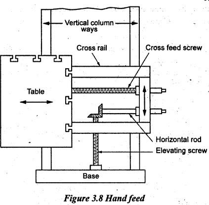
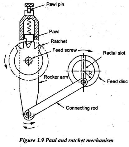
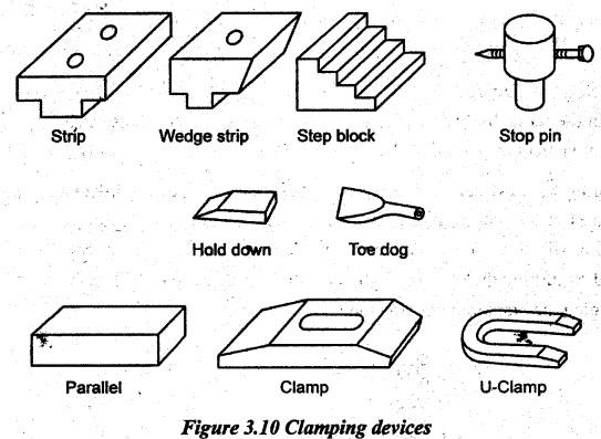
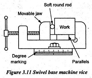
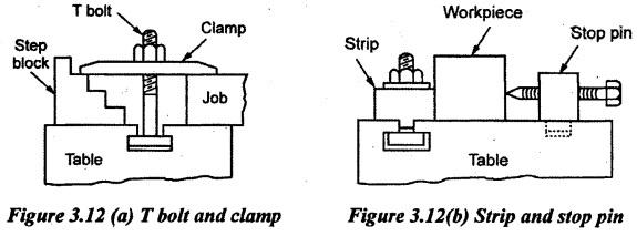
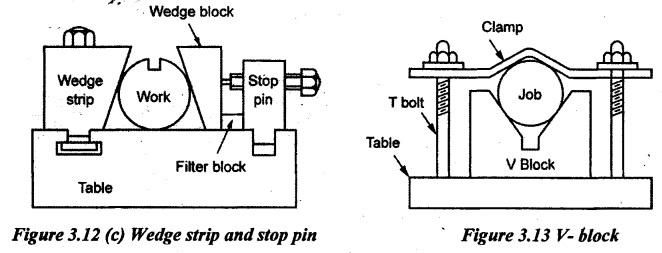
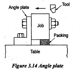
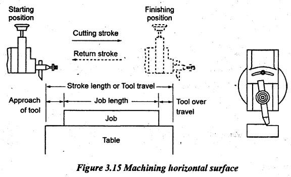
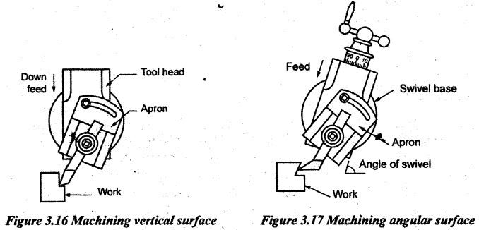
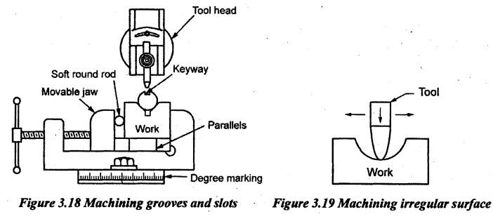
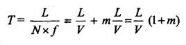
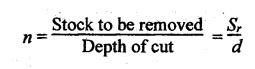
Unit - 3 RECIPROCATING MACHINE TOOLS Reciprocating machine tools: shaper, planer, slotter: Types and operations- Hole making: Drilling, reaming, boring, tapping, type of milling operations-attachments- types of milling cutters - machining time calculation - Gear cutting, gear hobbing and gear shaping gear finishing methods Abrasive processes: grinding wheel specifications and selection, types of grinding process - cylindrical grinding, surface grinding, centerless grinding, internal grinding - micro finishing methods. The one and only basic machine is a lathe. Except the lathe, other basic machines are shaper, planer, slotter, drilling, grinding, boring, milling and broaching machines. Among these machines, shaper, planer and slotter are called reciprocating machines because in these machines, the tool or workpiece moves forward and backward in a straight line over the other for machining the flat surfaces such as horizontal, vertical or inclined surfaces. Single point cutting tools are mainly used in these machines. Drilling, grinding, boring, milling and broaching machines are not used for machining flat surfaces but they are performing specific operations by using a multi-point cutting tool. Shaping machine is simply called a shaper having a reciprocating type of machine tool with single point cutting tool is used to produce flat surfaces. The flat surface may be horizontal, vertical or inclined. It has the three important parts such as a table, tool head and ram. The tool head is fitted at the front end of the ram while the job is rigidly fixed on the table. The tool is mounted on the tool post or head. The ram reciprocates along with the tool to remove the metal during forward stroke called cutting stroke. The tool does not cut the metal during return stroke, called idle stroke. Therefore, one pass is the combination of one forward and one return stroke or one cutting and one idle stroke. So, the idle stroke time is reduced by increasing the speed of the return stroke. It means, the speed of cutting stroke will be lower than the speed of return stroke. It is done to reduce the time required for one pass. Hence, the overall time required will drastically be reduced. This quick return of the ram during idle stroke is obtained by a quick return mechanism. At the end of each cutting stroke, the feed (depth of cut) is given. Various types of flat surfaces can be machined by the shaper as follows: 1. The table is moved in a cross-wise direction to machine the horizontal surfaces. 2. The tool head is moved perpendicular to the table in downward direction to machine the vertical surfaces. 3. The tool head is fed at an angle to produce inclined surfaces. 1. CLASSIFICATION OF SHAPING MACHINES Generally, shapers are classified as follows. 1. According to the type of driving mechanism a. Crank drive type b. Whitworth driving mechanism type c. Hydraulic drive type. 2. According to the position of ram a. Horizontal shaper b. Vertical shaper c. Travelling head shaper. 3. According to the table design a. Standard or plain shaper b. Universal shaper. 4. According to the type of cutting stroke a. Push out type b. Draw cut type. 2. TYPES OF SHAPING MACHINES The following are the types of shaper which are briefly described below: (a) Standard or Plain shaper This type of shaper has all above-described parts. In addition, it has a plain table called plain shaper, and the horizontal and vertical movement of the table with or without vertical supports at its front. So, it can be adjusted to any suitable height of the workpiece. Usually, the metal is removed during forward stroke, called push type shaper. (b) Universal shaper It has all parts similar to a standard shaper. Additionally, there is a special provision of the table which can be swiveled to an axis parallel to the ram movement. The swivel base is graduated in degrees. (c) Draw cut shaper It has all principal parts but it is heavier than a plain type. The main difference in this type of shaper is that the metal will be cut during return stroke. During cutting stroke, the tool draws the work towards the column called draw cut shaper. So, the cutting tool is fitted in a reverse direction. Hence, heavy cuts are possible and vibration is eliminated. 3. SIZE OF SHAPING MACHINES Generally, the specifications of a typical shaper are listed below. 1. Maximum length of the stroke 2. Maximum crosswise movement of the table 3. Maximum vertical adjustment of the table 4. Type of driving mechanism 5. Power of the motor 6. Available speed and feed 7. Type of shaper 8. Floor space required 9. Total weight of the shaper 10. Ratio of cutting stroke time to return stroke time. 4. PRINCIPAL PARTS OF A SHAPING MACHINE The different parts of a shaping machine are listed and described below. 1. Base 2. Column 3. Cross rail 4. Saddle 5. Table 6. Ram 7. Tool head. 1. Base: The base is heavy and robust in construction which is made of cast iron by a casting process. It is the only part to support all other parts because all parts are mounted at the top of this base. So, it should be made to absorb vibrations due to load and cutting forces while machining. 2. Column: The column has a box type structure which is made of cast iron. The inside surface is made as hollow to reduce the total weight of the shaper. It is mounted on the base. The ram driving (Quick return) mechanism is housed. The two guide ways are provided at the top. The ram reciprocates on this guide way. Similarly, there are two guide ways at the front vertical face of the column to move the cross rail along these guide ways. 3. Cross rail: It is also heavy in construction made of cast iron. It slides on the front vertical ways of the column with two mechanisms. Among them, one is for elevating the table and the other one is for cross travel of the table. A saddle slides over two guide ways already provided on the front face of the cross slide. The crosswise movement of the table is obtained by a cross feed screw and the vertical movement of the cross rail is obtained by an elevating screw. 4. Saddle: It is mounted on the cross rail which holds the table in position without any shake. 5. Table: It is also a box type rectangular hollow cast iron block. This table slides along the horizontal guide ways of the cross rail. The work is held on the table. The table has machined surfaces at the top and sides and it has T-slots for clamping work. It can vertically be moved by the elevating screw. An adjustable table support supports the front face of the table. 6. Ram: Ram is made of cast iron and has cross ribs for rigidity. Generally, it is a reciprocating type which slides over the guide ways at the top of the column. It is connected to driving mechanism of any one type and it also carries the tool head at the front end. 7. Tool head: Tool head is used to hold the tool rigidly. It is having swivel base with degree graduation. So, the tool head can be swiveled to any angle as required. The tool head has a vertical slide and apron to provide vertical and angular feeds to the tool. A feed screw with graduated dial moves the vertical slide vertically to set the accurate movement. The apron is clamped upon the vertical slide which can be tilted to right or left and also clamped at a correct position. The clapper box hinges a tool block already fitted with the apron. The tool block holds a tool post to mount the tool. During cutting stroke, the tool block fits rigidly inside the clapper box. During return stroke, the tool block lifts out of a clapper box to avoid rubbing of the tool on the job. 5. QUICK RETURN MECHANISM To convert the rotary motion of a motor into reciprocating motion of the tool, the various types of drives are provided in the shaper because the metal is removed during forward stroke. But no metal is cut during return stroke. Due to this, the time taken for the return stroke should be reduced by making the return stroke faster than the cutting stroke. It is achieved by some quick return mechanisms. The following three types of quick return mechanisms are used in the shaper. 1. Hydraulic drive 2. Crank and slotted link mechanism 3.. Whitworth quick return mechanism. 1. Hydraulic Drive A piston reciprocates within the hydraulic cylinder. A piston rod is connected between piston and ram. So, the ram reciprocates along with the piston. Two ports are provided near each end of the cylinder. A four-way control valve connects these two ports with the reservoir. The reservoir connects the valve through a drain pipe and a supply pipe. The supply pipe is again connected to the reservoir by a pump and relief valve. The valve is actuated by the lever and trip dog fitted to the ram. Oil is sucked by a gear pump from the reservoir at a particular pressure. This high- pressure oil goes to the cylinder through a four-way valve. The oil is allowed from the pump to the left side of the piston which forces the piston to move the ram towards right (R). It is called forward or cutting stroke. In this stroke, oil flows out to the right side entry to the reservoir through the four-way valve and drain pipe. The lever hits the trip dog (P1) at the end of this stroke. Now, the lever position is changed. Due to this, the supply pipe supplies the oil to the right side of the piston which moves the ram towards left (L), called return stroke or non-cutting stroke. During this stroke, the high-pressure oil of the same quantity covers less area on the cylinder due to the piston rod which increases the pressure. Hence, the return stroke is faster. Advantages of hydraulic drive: 1. Smooth cutting operation can be obtained by uniform speed. 2. Changing of cutting speed is easier. 3. Higher cutting to return ratio can be obtained. 4. Infinite range of cutting speeds'is available. 5. The operation is safe due to the relief valve fitted. 6. Stroke length can easily be adjusted without stopping the machine. 2. Crank and Slotted Link Mechanism In this mechanism, the ram is actuated by gear drives associated with the electric motor. First, the electric motor drives the pinion gear. Then, the pinion gear drives the bull gear which rotates in the opposite direction due to external gear meshing. A radial slide is provided on the bull gear. A sliding block is assembled on this slide. The block can be positioned in the radial direction by rotating the stroke adjustment screw. The bull gear has a- crank pin which is connected to the sliding block. A rocker arm is freely fitted to this crank pin. The sliding block slides in the slot provided in the rocker arm called slotted link. The bottom end of the rocker arm is pivoted and its upper end has a fork which is connected to the ram block by a pin. When the pinion gear rotates along with the bull gear, the crank will also rotate. Due to this, the rocker arm sliding block also rotates in the same circle. Simultaneously, the sliding block slides up and down in the slot. This movement is transmitted to the ram which reciprocates. Hence, the rotary motion is converted into reciprocating motion. 3. Whitworth Quick Return Mechanism From Figure 3.5, A1 and A2 are rear and forward extreme positions of the link. S1 and S2 are two extreme positions of a crank pin. During forward stroke, the link moves from A1 and A2 as the sliding block moves from S1 and S2 in the clockwise direction at an angle of α. During return stroke, the sliding block goes from S2 to S1 in the clockwise direction through an angle of β. But, the speed of bull gear is constant throughout. Therefore, the time taken during these two strokes is directly proportional to these angles a and β. But the angle β is smaller than α. So, the time taken by the return stroke will be reduced. The value of m varies from 2:1 to 3:2. Figure 3.6 illustrates the arrangement of various elements in Whitworth quick return mechanism. The shaft of an electric motor drives the pinion which rotates the bull gear. The bull gear has a crank pin. A sliding block slides over this crankpin and it slides inside the slot of a crank plate. This crank plate is eccentrically pivoted at point S. A connecting rod connects the crank plate by a pin at P at one end and ram at the other end M. When the pinion rotates, the bull is also rotated along with the crank pin. At the same time, the sliding block slides in the slot provided on the crank plate. It makes the ram to move up and down (reciprocating motion) by the connecting rod. The two important cases are discussed below. 1. When the pin A is at X, the ram will be in forward stroke. At that time, the bull gear rotates in the anticlockwise direction at an angle of α. 2. When the bull gear rotates further in the same direction from Y to X at an angle of β, the return stroke will take place. Here, the angle β is less than α. So, the time taken for the return stroke is reduced. Stroke length adjustment: The stroke length can be adjusted by moving the crank pin in the radial direction with a sliding block by an adjustment screw. It is rotated by a handle. The following two important points are to be remembered while adjusting the stroke length. 1. If the crank pin is adjusted near the centre of the bull gear, the rocker arm reciprocates for a smaller distance. Therefore, the stroke is reduced. 2. If the crank pin is adjusted in such way to be away from the centre of the bull gear, the rocker arm reciprocates for a larger distance. So, the stroke length is increased. 3. The stroke length should always be greater than the work length. i.e. Some amount of approach and over travel or overrun should be provided to the tool movement. Reasons for making the stroke length greater than work length: 1. To obtain the good surface finish. 2. To avoid rubbing of the tool on the work surface. 3. To allow sufficient time for giving cross feed. 4. To allow sufficient time for the clapper box to attain its proper seat for cutting. 5. To allow the ram for obtaining the proper cutting speed. Position adjustment: The following steps are listed below to adjust the position. 1. The clamping handle is loosened. 2. The stroke position hand wheel is rotated to rotate the screw inside the ram to make the ram movement both in forward and backward directions. 3. Finally, the clamping handle is tightened to adjust the position of stroke. 6. FEED MECHANISMS IN SHAPING MACHINES The mechanism through which the feed is given at the end of each return stroke is known as feed mechanism. It may be anyone of the following three types such as horizontal, vertical and inclined feed mechanisms. Both vertical and inclined feeds are given by rotating the hand wheel of the cross feed screw on the tool head by hand. 1. Hand Feed If the table is moved perpendicular to the ram movement, it is called cross feed. It is given by rotating the hand wheel of the cross feed screws. The vertical adjustment to hold the workpiece at various heights is made by rotating the elevating screw through the horizontal rod. Both vertical and angular feeds are given by the tool head. But the only difference in the angular feed is that the feed will be given after setting the work to its required angle. 2. Automatic Table Feed The automatic feed for the shaper table is given by a pawl and ratchet mechanism. This mechanism is connected with the rocker arm and connecting rod. Finally, it is connected with the driving disc having T-slots through a crank pin. The pawl is connected with pin and knob through the spring. The pawl is freely slipped up and down when the ratchet wheel rotates. During the first half revolution of the disc in the clockwise direction, the rocker arm rotates in the same direction but the pawl slips over the teeth of the ratchet wheel at that time and no movement is given to the table. This movement takes place only during cutting stroke. During the next half revolution of the disc in the same clockwise direction, the rocker arm rotates in the anticlockwise direction. Therefore, the pawl again slips over the teeth of the ratchet wheel. It takes place only on the return stroke. The reverse feed mechanism is obtained by turning the pawl through 180° after lifting the pawl. Then the cross feed is varied by changing the crank pin position radially on the disc. 7. WORK HOLDING DEVICES FOR SHAPING MACHINES The workpiece should tightly be clamped by using some holding devices in a shaper called work holding devices. These devices are selected depending on the shape and size of the job, and the type of operation to be performed. Usually, the clamping devices such as wedge strip, step block, stop pin, toe dog, hold down, parallel, clamp and U-clamp etc. are used as shown in Figure 3.10 The following methods are commonly used to hold the workpieces. (a) Clamp in a vice: Work is held quickly in a swivel base machine vice between two jaws as shown in Figure 3.11. Parallels are used to raise and set small works. It should not spoil the machined surface of work. (b) Clamping on the table: 1. The work is clamped by a T-bolt, step block and clamp as shown in Figure 3.12 (a). The height of the step should approximately be equal to the height of work. 'T' bolts should be placed near the work. 2. The work is held between the strip and stop pin as shown in Figure 3.12 (b). Tightening the stop pin screws are done by butting the work with a strip. Due to non-interference of clamps, the machining process can be performed on the entire surface. 3. Another method of clamping the workpiece is that the work is held between the wedge strip and stop pin as shown in Figure 3.12 (c). The work is clamped between two-wedge blocks. Then, it is firmly gripped by tightening the stop pin screws. (c) Clamping on a V-block: The small cylindrical workpieces are held on the V block and clamped by using 'T' bolts as shown in Figure 3.13. Machining can be done on the surface free from clamps. (d) Clamping on angle plate: The irregular shape of the workpiece is held on angle plates. The details are shown in Figure 3.14. The work is clamped by bolts. The packing pieces or wedges are used to give support the work wherever it is necessary. (e) Fixture: The fixture is a specially designed work holding device for the particular type of workpiece. It uses a combination of T-bolts, V-blocks and clamps. Locating, clamping and unloading of work can easily and quickly be done. The total production time and cost are reduced. The accuracy of machining is improved. 8. TOOLS USED IN SHAPING MACHINES Usually, the shaping tools are made of HSS or forged tools. It is a single point cutting tool. It is made to various clearance angles. It should make to withstanding shock load during starting of cut. The tools are classified as follows. 1. According to the shape (a) Straight tool (b) Cranked tool (c) Goose-necked tool. 2. According to the direction of cutting (a) Left-hand tool (b) Right-hand tool. 3. According to the finish required (a) Roughing tool (b) Finishing tool. 4. According to the type of operation (a) Down cutting tool (b) Parting off tool (c) Squaring tool (d) Side recessing tool. 5. According to the shape of the cutting edge. (a) Round nose tool (b) Square nose tool. 9. OPERATIONS PERFORMED ON SHAPING MACHINES The following operations can be performed on a shaper. 1. Machining horizontal surface 2. Machining vertical surface 3. Machining angular surface 4. Machining slots, grooves and keyways 5. Machining irregular surfaces. 1. Machining Horizontal Surface The work is held on a table and the tool is fitted on the tool post with minimum overhung. It should prevent the rubbing of the tool on the work while returning. The tool is vertically adjusted by some clearance and the stroke length is set longer than the workpiece i.e. 12 mm tool approach and 8mm tool overrun are added to the length of the work as shown in Figure 3.15. Then the proper cutting speed and feed are chosen. During starting of the shaper to machine the work, the tool is just made to touch the job. Afterwards, the depth of cut is given at the end of each return stroke by rotating the down feed screw. In any machines, the roughing cut is performed by giving more depth of cut with slow cutting speed and faster feed. Similarly, the finishing cut is performed by giving less depth of cut with faster cutting speed and slow feed. 2. Machining Vertical Surface The job is held on the table and the tool is set on the tool holder. The tool position and the stroke length are adjusted to a required dimension. Then the value on the vertical slide dial is set at zero. The apron is swiveled as shown in Figure 3.16 to avoid the rubbing of the tool on the work surface during return stroke. The depth of cut is given by raising or elevating the table. Feed is given by rotating the down feed screws of tool head at the end of the return stroke. 3. Machining Angular Surface The job is mounted on the table and the tool is set at required angle on the tool head as shown in Figure 3.17. Position and stroke lengths are adjusted. Also, the proper cutting speed and feed are chosen. The apron is set away from the machining surface. The method of giving depth of cut and feed are similar to machining the vertical surface. For example, to make the dovetail shape on the right-hand side of the workpiece, the vertical slide with the right-hand tool is set at the required angle on the right-side of the work. By giving the feed and depth of cut, the right side dovetail is finished. 4. Machining Slots, Grooves and Keyways The work is held in a vice using 'V' blocks and parallels. First, a hole is drilled to a required keyway depth at the end of the workpiece. The diameter of the hole should be greater than the width of the keyway. Then, the position and stroke length are adjusted. The keyway-cutting tool is set on the tool head. Finally, the external keyway is machined with reduced speed. 5. Machining Irregular Surface For machining the irregular surface, a round nose tool is set on the tool head. By giving both the cross feed and vertical feed simultaneously, the irregular surface is obtained. The cross feed is given through the table and the vertical feed is given by the tool head. The apron is fitted to some angle away from the machined surface to avoid the rubbing of the tool on the work during return stroke. 10. ADVANTAGES OF SHAPING MACHINES (i) Single point cutting tools used in shapers are cheap. (ii) The tools can be easily grounded to any desirable shape. (iii) The simplicity and ease of holding work, its easy adjustment and the simple tool give the shaper its great flexibility. (iv) Shaper set up is very is very quick and easy and it can be readily changed from one job to another. (v) Thin or fragile jobs can be conveniently machined on shapers because of lower cutting forces. 11. SHAPER LIMITATIONS (i) The shaper is not suitable for generating flat surfaces on very large parts because of the limitations on the stroke and overhang of the ram. (ii) Planer solved this problem by applying the linear primary motion to the workpiece and feeding the tool at right angles to this motion. (iii) The primary motion is accomplished by a rack and pinion drive using a variable speed motor. 12. CUTTING SPEED, FEED, DEPTH OF CUT AND MACHINING TIME CALCULATIONS FOR SHAPING MACHINES 1. Cutting speed (V): It is the velocity at which the metal is removed by the tool. where L - Length of the cutting stroke N – Speed in rpm m - Ratio between the cutting time and return time. 2. Feed (f): The relative movement of the tool with respect to the workpiece axis is known as feed. 3. Depth of cut (t): The amount of metal removed in one stroke or in one cut is known as depth of cut. 4. Machining time (T): The time required for machining the work surface to the required dimensions. where L - length of stroke = l + Approach length + Over run N - Speed in rpm f - Feed per stoke l - Workpiece length L/V - Time for cutting stroke mL/V - Time for return stroke. 5. Number of strokes required (SN): It is the ratio between the width of work (W) and feed per stroke. 6. Total machining time (Tt): It is the time required for machining the entire surface of the work as per requirements. Tt = T × SN 7. Metal removal rate (MRR): It is the volume of metal removed per unit time. MRR = f d L S where f - Feed d - Depth of cut L - Length of work S - Strokes per minute. 8. Power required: P = k × MRR where k - Machining constant. 9. Number pass:1. SHAPING MACHINE

Manufacturing Technology: Unit III: Reciprocating Machine Tools : Tag: : Reciprocating Machine Tools - Manufacturing Technology - Reciprocating machine tools
Related Topics
Related Subjects

Manufacturing Technology
ME3493 4th semester Mechanical Dept | 2021 Regulation | 4th Semester Mechanical Dept 2021 Regulation