Hydraulics and Pneumatics: Unit II: Hydraulic Actuators and Control Components
proportional direction control valve
Construction, Operation, Graphic Symbol
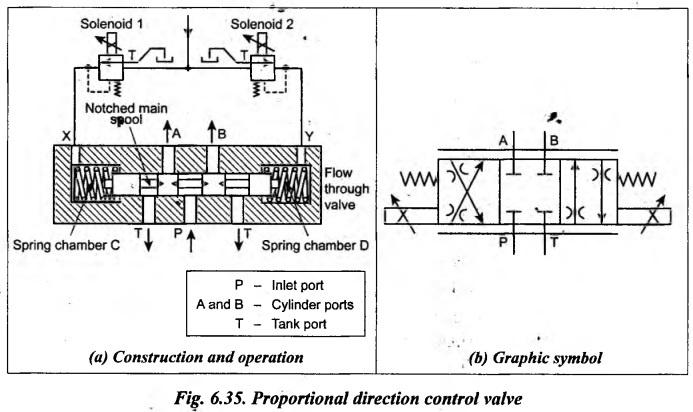
The construction and operation of a typical proportional direction control valve is illustrated in Fig.6.35(a).
PROPORTIONAL DIRECTION CONTROL VALVE The construction and operation of a typical proportional direction control valve is illustrated in Fig.6.35(a). When solenoid 1 is energized, the pressure is applied to pilot port X. This causes the spool to move towards right against the control spring. As the main spool lands are notched, the spool movement to the right will allow the fluid flow from port P to B and from port A to Ț. When the solenoid is de-energized, the spring chamber C depressurises and the control spring centralises the spool to its normal position. Similarly when solenoid 2 is energized, the pressure is applied to pilot port Y. This causes the spool to move towards left against the control spring. Now the fluid flows from port P to A and from port B to T. When the solenoid 2 is de-energized, the spool returns to its normal position. Thus the movement of the spool is proportional to the pressures applied to the pilot ports X and Y, which in turn proportional to the current in solenoids 1 and 2. Fig.6.35(b) shows the graphic symbol of the proportional direction control valve.1. Construction
2. Operation
3. Graphic Symbol
Hydraulics and Pneumatics: Unit II: Hydraulic Actuators and Control Components : Tag: : Construction, Operation, Graphic Symbol - proportional direction control valve
Related Topics
Related Subjects

Hydraulics and Pneumatics
ME3492 4th semester Mechanical Dept | 2021 Regulation | 4th Semester Mechanical Dept 2021 Regulation