Engineering Graphics: Unit II (b): Projections of Points
Projections of Points
Engineering Graphics (EG)
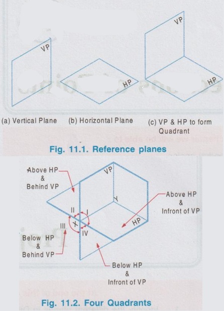
The point may be situated in any one of these four quadrants (or) may lie in the principal planes.
Chapter -11 Projections of Points At the end of this chapter we will be able to: List out the possible positions of a point in Dihedral angles. 1. Identify the different planes in Dihedral angles. 2. Describe the method of drawing orthographic projections of a point. 3. Draw the projections of a point located in all the four Quadrants with various positions. 4. Interprete the given projections of a point and determine its position with respect to the principal planes. Orthographic projections of a three dimensional object was shown in chapter 9 using the three reference planes, It is to be recalled now that the object was placed in first quadrant (as per IS method) and parallel to both vertical and horizontal planes ie., the projections are perpendicular to the opponent planes. But in engineering drawing some times the orthographic views of solids will be required with different position of solids like inclined to VP (or) inclined to HP (or) inclined to both the planes. So it is required to develop the orthographic views of solids with different position of its axis with respect to the reference planes. As we know, a solid is formed by three dimensions measured in three mutually perpendicular directions (example: a prism, having three dimensions, length, breadth and height). If one of the dimensions of a solid figure is made zero, then the objects becomes a two dimensional figure, known as plane (example: rectangle, having two dimensions, length and breadth). Further, if one more dimension in a plane figure is made zero, the plane figure is changed into a line, having only one dimension of length. In a line, if the remaining dimension is also removed, the line is shortened into zero length, and forms a point. Therefore a point may be considered as, the smallest and dimensionless object in three dimensional geometry which is represented by a dot in the drawings. This chapter explains the method of drawing of orthographic projections of points with respect to the reference planes. Having understood the projection of points, projections of lines, plane figures and solid figures can be developed, which are explained in the proceeding chapters. Two reference planes, Vertical plane (Fig. 11.1(a)) and Horizontal plane (Fig. 11.1(b)) are intersected at right angles to each other (Fig. 11.1 (c)), to form Di-hedral angles, as shown in Fig. 11.2. In dihedral angles, four quadrants are formed. These quadrants are named as I, II, III and IV in anticlockwise direction and distinguished with respect to the reference planes as below: The point may be situated in any one of these four quadrants (or) may lie in the principal planes. INTRODUCTION
Engineering Graphics: Unit II (b): Projections of Points : Tag: : Engineering Graphics (EG) - Projections of Points
Related Topics
Related Subjects

Engineering Graphics
GE3251 eg 2nd semester | 2021 Regulation | 2nd Semester Common to all Dept 2021 Regulation